

Arduino Lesson 2
2. Digital Write
Blink a LED with digital write
Components Required
Buy
Introduction
In this example, you are learning how to turn on and off a LED or any other actuator which can be controlled by a digital output such as relay, bulb, motor.
Learning Outcomes
From this example, you’ll get an understanding about,
- Pin Mode
- Digital Write
- Delay Functions
Theory
A digital output allows you to control a voltage with an electronic device. If the device instructs the output to be high, the output will produce a voltage (generally about 5 or 3.3 volts). If the device instructs the output below, it is connected to the ground and produces no voltage. Here, Magicbit is the device and the output voltage is either 3.3V for HIGH and 0V for LOW.
Methodology
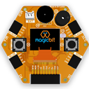
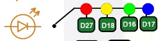
Magicbit equipped with four onboard LED in Magicbit development board, Lets select yellow LED (which is wired to D16)
By setting the output state to high of the LED pin will turn on the LED and by setting the output state to LOW will turn off the LED.
Code
void setup(){
   pinMode(16,OUTPUT);
}
void loop(){
   digitalWrite(16,HIGH);
   delay(1000);
   digitalWrite(16,LOW);
   delay(1000);
}
Explanation
pinMode(pin, Mode): Configures the specified pin to behave either as an input or an output. Here, we use the pin as an output
digitalWrite(pin No, State): Write a HIGH or a LOW value to a digital pin. Pin mode must be set up for the same pin in Setup to work this function properly.
delay(ms): Pauses the program for the amount of time (in milliseconds) specified as a parameter. (note, 1000 milliseconds equals one second)
Note: Write code for a Knight Rider pattern using onboard LEDs of Magicbit