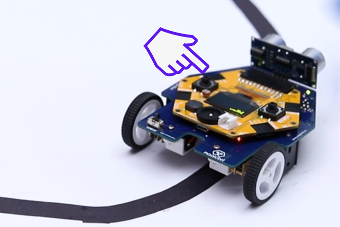
Simple line follower Robot
Components Required
Introduction
In this tutorial, we will learn how to make a simple line follower robot with magicbit using arduino IDE. Line follower is a robot that is widely used in various industrial and domestic applications such as carrying goods, delivery services, and transportation.
Basically, the function of a line follower is to follow a line or set of markers of a specific color, mostly a black line on a white background or vice versa.
A basic line follower robot consists of 2 line sensors and 2 motors.
What You Need
- Magicbit
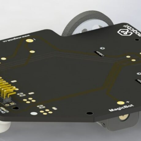
- Magicbot
- Black color Tape
- White surface/floor
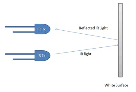
How IR sensor work
IR reflectance sensor consists of IR emitter and an IR receiver. IR transmits infrared lights. When infrared rays fall on a white surface, it’s reflected back on to the phototransistor which generates a change of currents, which can be turned into a change of voltage using a fixed resistor in series. When IR light falls on a black surface, light is absorbed by the black surface and minimal amount of light is reflected back to the photodiode. This difference in reflected light amount changes the voltage at the output, which can be used to identify whether the sensor is on a black surface or a white surface.
Method
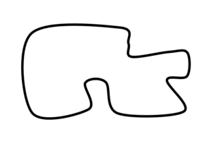
Setting up the arena
This robot finds its way by using color changes on the surface. so its suitable colors are black and white. Therefore Make a 2cm wide black color line on the white surface. You can use some black color tape for that.
Better to make a closed loop line. This allows the robot to work continuously.
Hardware Setup
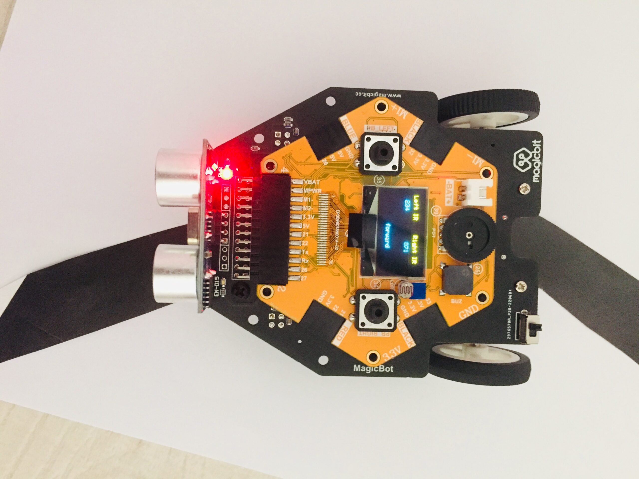
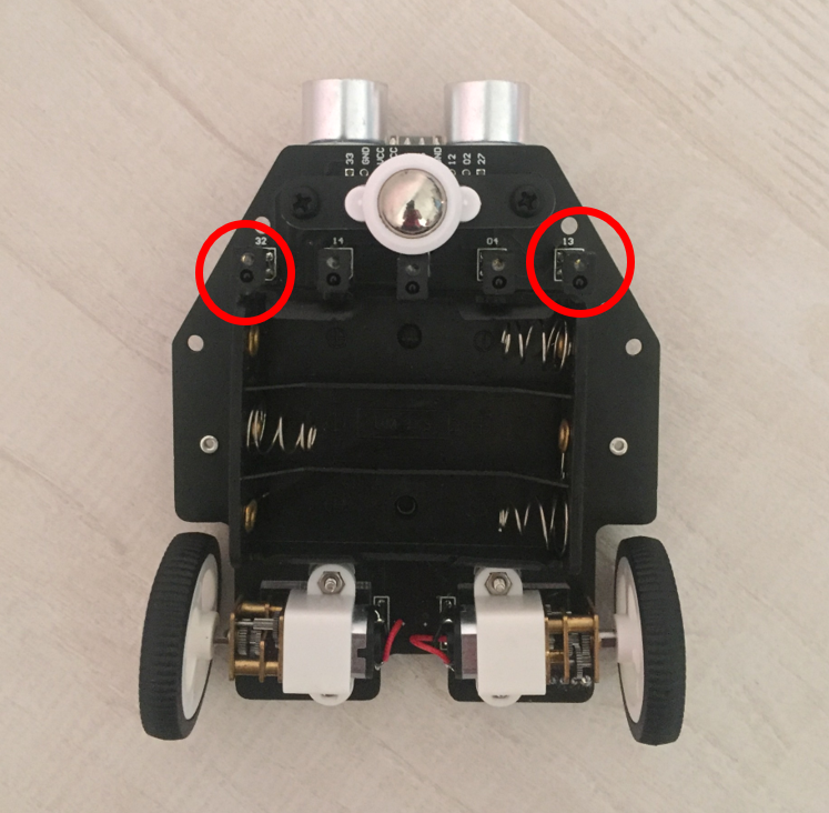
MagicBot – Just connect the magicbit board with a magicbot. Then, download the Arduino code and upload the code onto your magicbit board.
Note- magicbot has 5 IR sensors, but in this project, we will only use IR1 and IR5.
Code
//Line Follower Robot
//Magicbit.cc

#include <ESP32Servo.h>
#include <Wire.h>
#include <Adafruit_SSD1306.h>

#define ir1 13  //IR sensor left
#define ir2 32  //IR sensor Right

#define M1A 17  //Motor diver pin -Left motor
#define M1B 16
#define M2A 18  //Motor diver pin -Right motor
#define M2B 27

#define SCREEN_WIDTH 128 // OLED display width, in pixels
#define SCREEN_HEIGHT 64 // OLED display height, in pixels
Adafruit_SSD1306 display(SCREEN_WIDTH, SCREEN_HEIGHT, &Wire, -1);

void setup() {

display.begin(SSD1306_SWITCHCAPVCC, 0x3C);
Serial.begin(115200);

pinMode(ir1, INPUT);
pinMode(ir2, INPUT);
pinMode(M1A, OUTPUT);
pinMode(M1B, OUTPUT);
pinMode(M2A, OUTPUT);
pinMode(M2B, OUTPUT);

display.clearDisplay();
}

void loop() {

 int Ls =analogRead(ir1); //Read IR data
 int Rs =analogRead(ir2);


  display.clearDisplay();
  display.setTextColor(WHITE);

    display.setCursor(2,5);
    display.println("Left IR");
    display.setCursor(10,18);
    display.println(Ls);

    display.setCursor(70,5);
    display.println("Right IR");
    display.setCursor(82,18);
    display.println(Rs);


 if(Ls < 1000 && Rs < 1000) {
     forward(100);
     //delay(10);
  }else if(Ls > 1000){
      Left(100);
      //delay(10);
  }else if(Rs >1000){
        Right(100);
        //delay(10);
  }
   display.display();
}

 void forward(int x) {
    analogWrite(M1A, x);
    analogWrite(M1B, 0);
    analogWrite(M2A, x);
    analogWrite(M2B, 0);

    display.setCursor(50,50);
    display.println("Forward");

}

void Left(int x) {
    analogWrite(M1A, 0);
    analogWrite(M1B, 0);
    analogWrite(M2A, x);
    analogWrite(M2B, 0);

   display.setCursor(40,50);
   display.println("Turn Left");
}

void Right(int x) {
    analogWrite(M1A, x);
    analogWrite(M1B, 0);
    analogWrite(M2A, 0);
    analogWrite(M2B, 0);

   display.setCursor(40,50);
   display.println("Turn Right");

}