
IR Remote
Duplicate an IR Remote using Magicbit
What is IR Communication?
IR communication is a common and inexpensive wireless communication technology. IR is very similar to visible light except it has a slightly longer wavelength. This means IR waves are undetectable to human eye, therefore it is perfect for wireless communication.
Introduction
In this project, we will use an infrared LED to send signals to a device. IR is often used in remotes because it is not visible to the human eye. Each button of the remote is assigned with a hexadecimal value. We will try to find this exact hexadecimal number for a button and send it to the device through an IR LED using a Magicbit. We have used IRremoteESP8266 library for this.
Components Required
Instructions
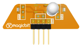
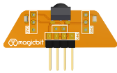
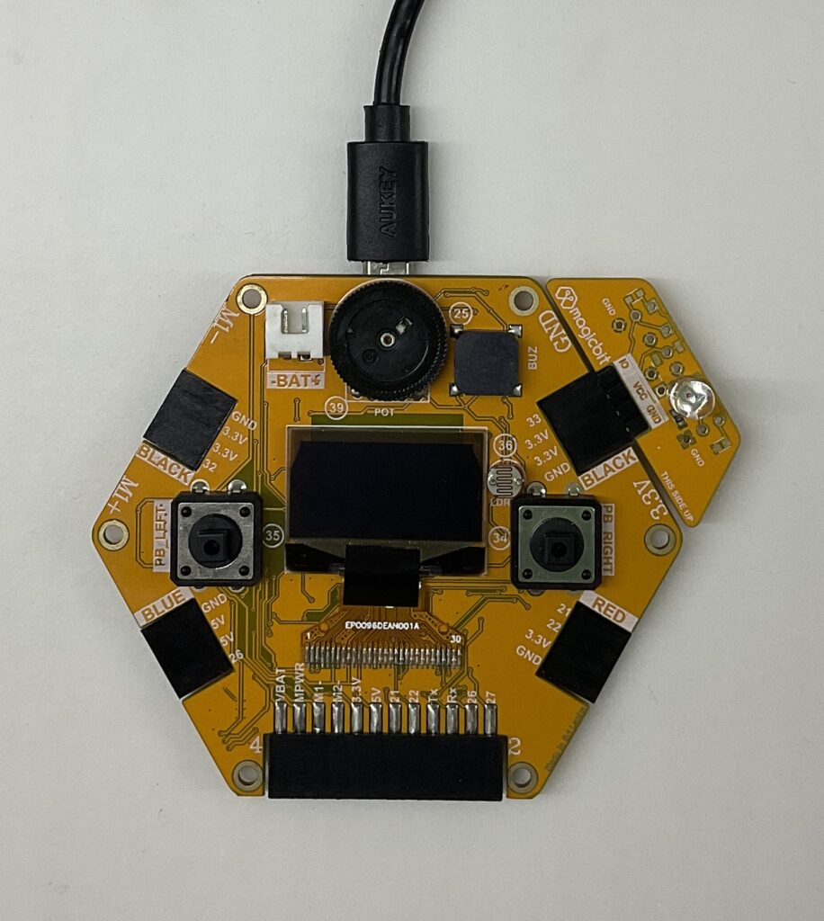
- First, connect the IR receiver to the Magicbit pin 32.
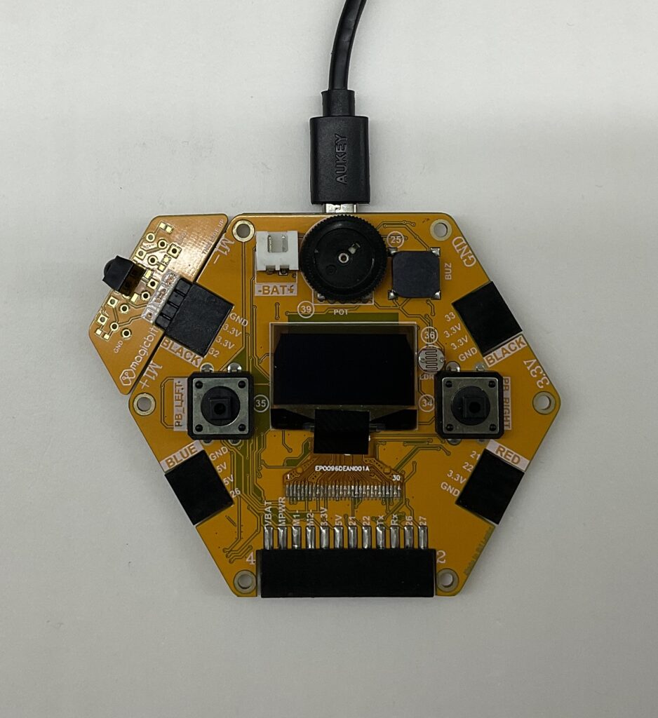
- Copy the code below and upload it to the Magicbit
#include <Arduino.h>
#include <assert.h>
#include <IRrecv.h>
#include <IRremoteESP8266.h>
#include <IRac.h>
#include <IRtext.h>
#include <IRutils.h>

// ==================== start of TUNEABLE PARAMETERS ====================
// Note: GPIO 16 won't work on the ESP8266 as it does not have interrupts.
// Note: GPIO 14 won't work on the ESP32-C3 as it causes the board to reboot.
#ifdef ARDUINO_ESP32C3_DEV
const uint16_t kRecvPin = 32;  // 14 on a ESP32-C3 causes a boot loop.
#else  // ARDUINO_ESP32C3_DEV
const uint16_t kRecvPin = 32;
#endif  // ARDUINO_ESP32C3_DEV

// The Serial connection baud rate.
// i.e. Status message will be sent to the PC at this baud rate.
// Try to avoid slow speeds like 9600, as you will miss messages and
// cause other problems. 115200 (or faster) is recommended.
// NOTE: Make sure you set your Serial Monitor to the same speed.
const uint32_t kBaudRate = 115200;

// As this program is a special purpose capture/decoder, let us use a larger
// than normal buffer so we can handle Air Conditioner remote codes.
const uint16_t kCaptureBufferSize = 1024;

// kTimeout is the Nr. of milli-Seconds of no-more-data before we consider a
// message ended.
// This parameter is an interesting trade-off. The longer the timeout, the more
// complex a message it can capture. e.g. Some device protocols will send
// multiple message packets in quick succession, like Air Conditioner remotes.
// Air Coniditioner protocols often have a considerable gap (20-40+ms) between
// packets.
// The downside of a large timeout value is a lot of less complex protocols
// send multiple messages when the remote's button is held down. The gap between
// them is often also around 20+ms. This can result in the raw data be 2-3+
// times larger than needed as it has captured 2-3+ messages in a single
// capture. Setting a low timeout value can resolve this.
// So, choosing the best kTimeout value for your use particular case is
// quite nuanced. Good luck and happy hunting.
// NOTE: Don't exceed kMaxTimeoutMs. Typically 130ms.
#if DECODE_AC
// Some A/C units have gaps in their protocols of ~40ms. e.g. Kelvinator
// A value this large may swallow repeats of some protocols
const uint8_t kTimeout = 50;
#else   // DECODE_AC
// Suits most messages, while not swallowing many repeats.
const uint8_t kTimeout = 15;
#endif  // DECODE_AC
// Alternatives:
// const uint8_t kTimeout = 90;
// Suits messages with big gaps like XMP-1 & some aircon units, but can
// accidentally swallow repeated messages in the rawData[] output.
//
// const uint8_t kTimeout = kMaxTimeoutMs;
// This will set it to our currently allowed maximum.
// Values this high are problematic because it is roughly the typical boundary
// where most messages repeat.
// e.g. It will stop decoding a message and start sending it to serial at
//      precisely the time when the next message is likely to be transmitted,
//      and may miss it.

// Set the smallest sized "UNKNOWN" message packets we actually care about.
// This value helps reduce the false-positive detection rate of IR background
// noise as real messages. The chances of background IR noise getting detected
// as a message increases with the length of the kTimeout value. (See above)
// The downside of setting this message too large is you can miss some valid
// short messages for protocols that this library doesn't yet decode.
//
// Set higher if you get lots of random short UNKNOWN messages when nothing
// should be sending a message.
// Set lower if you are sure your setup is working, but it doesn't see messages
// from your device. (e.g. Other IR remotes work.)
// NOTE: Set this value very high to effectively turn off UNKNOWN detection.
const uint16_t kMinUnknownSize = 12;

// How much percentage lee way do we give to incoming signals in order to match
// it?
// e.g. +/- 25% (default) to an expected value of 500 would mean matching a
//      value between 375 & 625 inclusive.
// Note: Default is 25(%). Going to a value >= 50(%) will cause some protocols
//       to no longer match correctly. In normal situations you probably do not
//       need to adjust this value. Typically that's when the library detects
//       your remote's message some of the time, but not all of the time.
const uint8_t kTolerancePercentage = kTolerance;  // kTolerance is normally 25%

// Legacy (No longer supported!)
//
// Change to `true` if you miss/need the old "Raw Timing[]" display.
#define LEGACY_TIMING_INFO false
// ==================== end of TUNEABLE PARAMETERS ====================

// Use turn on the save buffer feature for more complete capture coverage.
IRrecv irrecv(kRecvPin, kCaptureBufferSize, kTimeout, true);
decode_results results;  // Somewhere to store the results

// This section of code runs only once at start-up.
void setup() {
#if defined(ESP8266)
  Serial.begin(kBaudRate, SERIAL_8N1, SERIAL_TX_ONLY);
#else  // ESP8266
  Serial.begin(kBaudRate, SERIAL_8N1);
#endif  // ESP8266
  while (!Serial)  // Wait for the serial connection to be establised.
    delay(50);
  // Perform a low level sanity checks that the compiler performs bit field
  // packing as we expect and Endianness is as we expect.
  assert(irutils::lowLevelSanityCheck() == 0);

  Serial.printf("\n" D_STR_IRRECVDUMP_STARTUP "\n", kRecvPin);
#if DECODE_HASH
  // Ignore messages with less than minimum on or off pulses.
  irrecv.setUnknownThreshold(kMinUnknownSize);
#endif  // DECODE_HASH
  irrecv.setTolerance(kTolerancePercentage);  // Override the default tolerance.
  irrecv.enableIRIn();  // Start the receiver
}

// The repeating section of the code
void loop() {
  // Check if the IR code has been received.
  if (irrecv.decode(&results)) {
    // Display a crude timestamp.
    uint32_t now = millis();
    Serial.printf(D_STR_TIMESTAMP " : %06u.%03u\n", now / 1000, now % 1000);
    // Check if we got an IR message that was to big for our capture buffer.
    if (results.overflow)
      Serial.printf(D_WARN_BUFFERFULL "\n", kCaptureBufferSize);
    // Display the library version the message was captured with.
    Serial.println(D_STR_LIBRARY "   : v" _IRREMOTEESP8266_VERSION_STR "\n");
    // Display the tolerance percentage if it has been change from the default.
    if (kTolerancePercentage != kTolerance)
      Serial.printf(D_STR_TOLERANCE " : %d%%\n", kTolerancePercentage);
    // Display the basic output of what we found.
    Serial.print(resultToHumanReadableBasic(&results));
    // Display any extra A/C info if we have it.
    String description = IRAcUtils::resultAcToString(&results);
    if (description.length()) Serial.println(D_STR_MESGDESC ": " + description);
    yield();  // Feed the WDT as the text output can take a while to print.
#if LEGACY_TIMING_INFO
    // Output legacy RAW timing info of the result.
    Serial.println(resultToTimingInfo(&results));
    yield();  // Feed the WDT (again)
#endif  // LEGACY_TIMING_INFO
    // Output the results as source code
    Serial.println(resultToSourceCode(&results));
    Serial.println();    // Blank line between entries
    yield();             // Feed the WDT (again)
  }
}
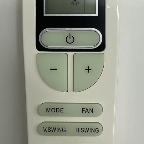
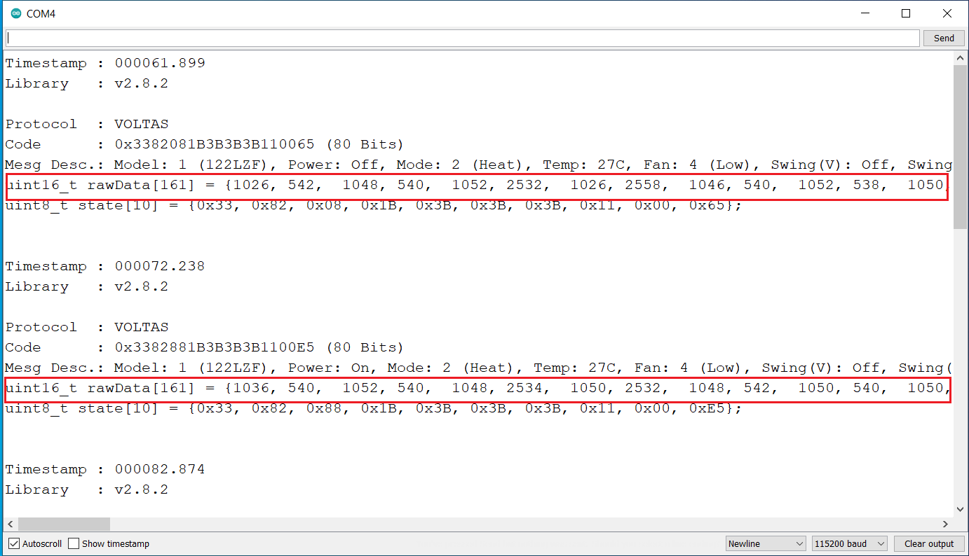
- Press the buttons that needed to be copied.
- Copy the corresponding raw data values.
- Now connect the IR sender LED to pin 33
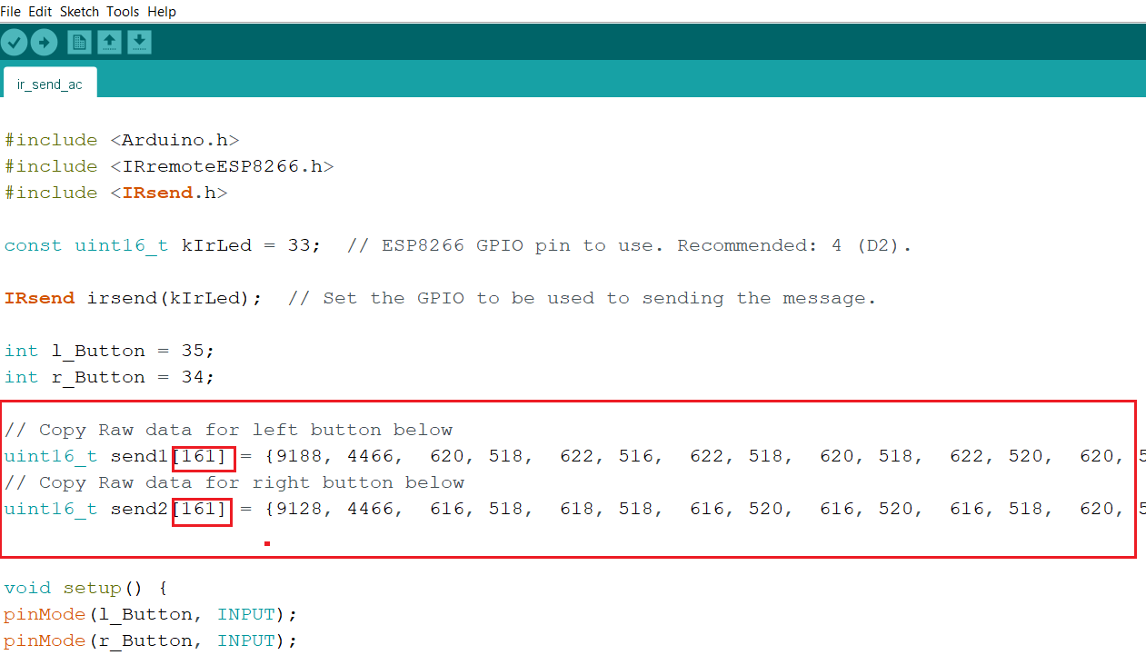
- Copy the second code below and edit the marked values with the copied values of raw data. (If you have a simple hex code, you can send it as a hexadecimal number)
#include <Arduino.h>
#include <IRremoteESP8266.h>
#include <IRsend.h>

const uint16_t kIrLed = 33;  // ESP8266 GPIO pin to use. Recommended: 4 (D2).

IRsend irsend(kIrLed);  // Set the GPIO to be used to sending the message.

int l_Button = 35;
int r_Button = 34;

// Copy Raw data for left button below
uint16_t send1[161] = {1028, 544, 1046, 546, 1044, 2538, 1044, 2538, 1044, 546, 1044, 546, 1046, 2538, 1042, 2542, 1042, 2540, 1042, 2540, 1044, 2540, 1044, 546, 1044, 2540, 1044, 546, 1044, 546, 1042, 548, 1042, 546, 1042, 546, 1042, 548, 1044, 546, 1042, 2540, 1044, 2542, 1042, 2544, 1040, 2542, 1040, 552, 1040, 550, 1038, 550, 1042, 2542, 1038, 2546, 1038, 552, 1038, 2546, 1036, 2546, 1038, 572, 1016, 554, 1038, 2566, 1016, 2544, 1040, 2566, 1018, 572, 1018, 2566, 1018, 2568, 1016, 572, 1018, 572, 1016, 2568, 1016, 2566, 1018, 2568, 1016, 576, 1014, 2568, 1014, 2568, 1016, 576, 1016, 574, 1014, 2568, 1016, 2570, 1016, 2568, 1014, 576, 1016, 2568, 1016, 2566, 1016, 572, 1016, 574, 1016, 574, 1016, 2568, 1016, 572, 1016, 574, 1016, 574, 1018, 2568, 1014, 574, 1016, 576, 1014, 576, 1014, 576, 1016, 574, 1014, 574, 1016, 576, 1014, 574, 1016, 2568, 1014, 2570, 1014, 2570, 1014, 2568, 1014, 2570, 1014, 576, 1012, 576, 1016, 574, 1016}; // VOLTAS
// Copy Raw data for right button below
uint16_t send2[161] = {1022, 548, 1042, 546, 1044, 2540, 1044, 2538, 1046, 546, 1042, 548, 1044, 2540, 1044, 2538, 1042, 2542, 1040, 2540, 1044, 2542, 1042, 548, 1044, 2538, 1042, 548, 1042, 546, 1044, 548, 1040, 2540, 1044, 546, 1042, 546, 1042, 548, 1042, 2540, 1042, 2542, 1040, 2542, 1040, 2544, 1040, 550, 1042, 548, 1040, 574, 1016, 2546, 1038, 2544, 1040, 552, 1038, 2546, 1038, 2544, 1038, 572, 1016, 576, 1016, 2564, 1018, 2568, 1014, 2568, 1016, 572, 1016, 2568, 1016, 2568, 1016, 574, 1016, 576, 1014, 2566, 1016, 2566, 1016, 2568, 1018, 572, 1014, 2568, 1014, 2568, 1016, 574, 1016, 574, 1014, 2568, 1016, 2566, 1018, 2566, 1016, 574, 1016, 2568, 1016, 2570, 1014, 574, 1016, 576, 1014, 576, 1014, 2568, 1016, 572, 1016, 574, 1014, 576, 1014, 2568, 1014, 576, 1014, 574, 1014, 578, 1014, 576, 1014, 574, 1016, 574, 1016, 572, 1016, 574, 1014, 574, 1016, 2568, 1014, 2568, 1014, 2568, 1016, 2570, 1014, 576, 1014, 574, 1014, 574, 1016}; // VOLTAS


void setup() {
pinMode(l_Button, INPUT);
pinMode(r_Button, INPUT);

  irsend.begin();
#if ESP8266
  Serial.begin(115200, SERIAL_8N1, SERIAL_TX_ONLY);
#else  // ESP8266
  Serial.begin(115200, SERIAL_8N1);
#endif  // ESP8266
}

void loop() {


  int l_state = digitalRead(l_Button);
  int r_state = digitalRead(r_Button);

  if (!l_state) {
    irsend.sendRaw(send1, 161, 38);  // send raw data
  }
    if (!r_state) {
    irsend.sendRaw(send2, 161, 38);  // send raw data
  }
  delay(200)
}
Don’t forget to edit the values below,
Be sure to edit the length as shown below.
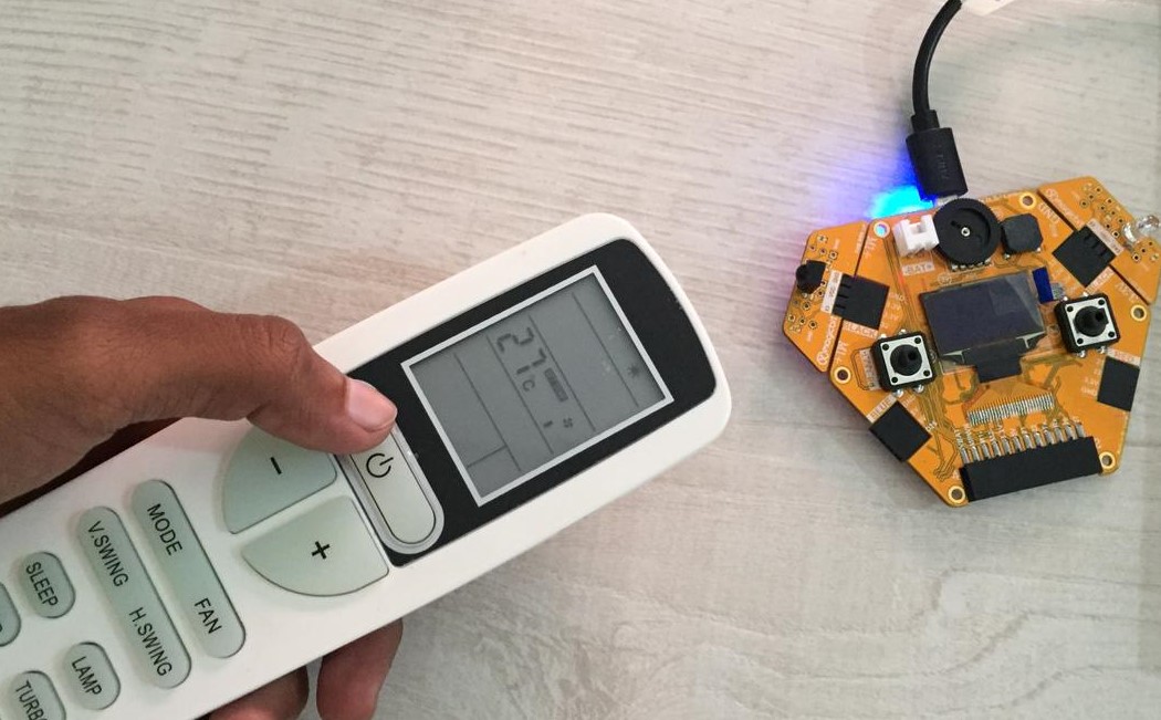
now your magicbit work as an IR remote.