
Magicbit is a feature-rich, easy-to-use, and cost-effective platform made for everyone. The inbuilt functionalities of Magicbit provide a unique advantage for users to learn and practice a wide range of application areas such as robotics, programming, Internet of Things(IoT) and electronics.
Magicbit is an innovation ecosystem with hardware, software, mobile app, educational content, community and partners. Integrated solutions can be developed more easily while exploring cross-platform options such as programming with any other software or connecting to any cloud IoT platform.
A frequently asked question about Magicbit is “What are the innovations I can develop with Magicbit?”. The answer to that would be “It has no limits”. Your creativity and innovative mindset have to decide the number of innovations you can do. After all, the world needs more solutions with technology to resolve some of the burning problems faced by mankind. Making technology accessible and available to everyone is the passion Magicbit team would like to share with everyone.
So, Welcome to the world of Magicbit, Let’s start your journey of innovation!
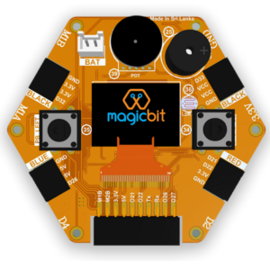
Magicbit board itself has many inbuilt features to support learning and innovation,
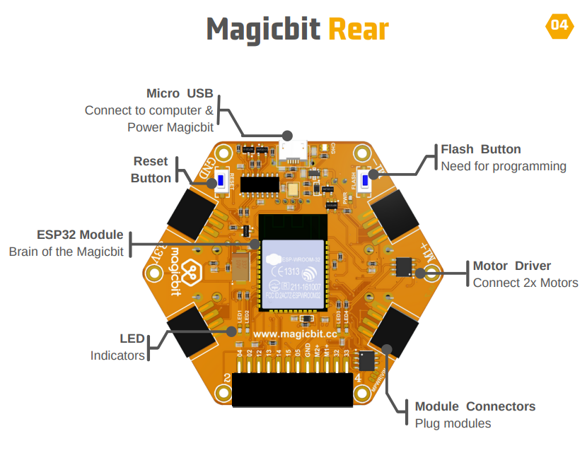
- High Performance – 240 MHz Speed, 4 MB Flash, 520 KB RAM
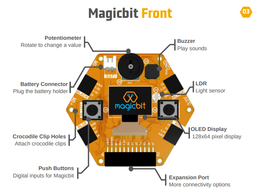
- On-board Sensors – Push Button, LDR, Potentiometer
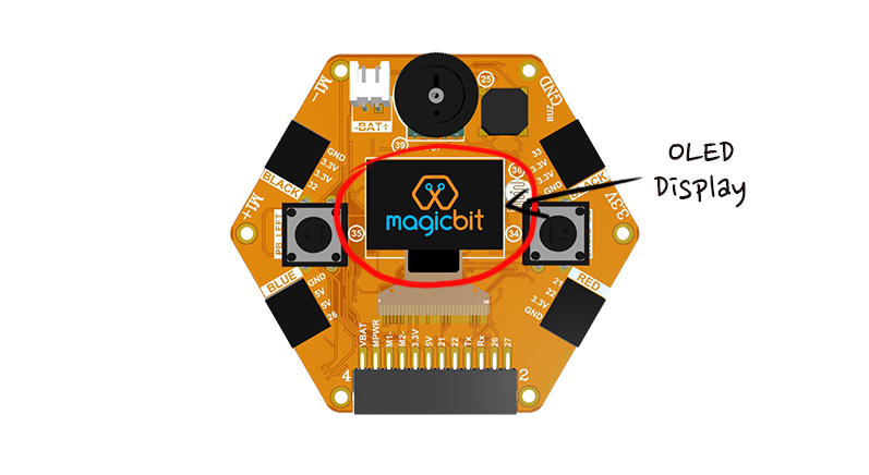
- On-board Actuators – OLED Display, Buzzer, Motor Driver
- Multiple Connectivity Options – USB, Bluetooth, Wifi
- Pluggable Modules – Plug-and-play design
- Li-ion battery charger
.
- Magicbit core
- Computer or Laptop
- Wifi connection with internet access
- USB cable
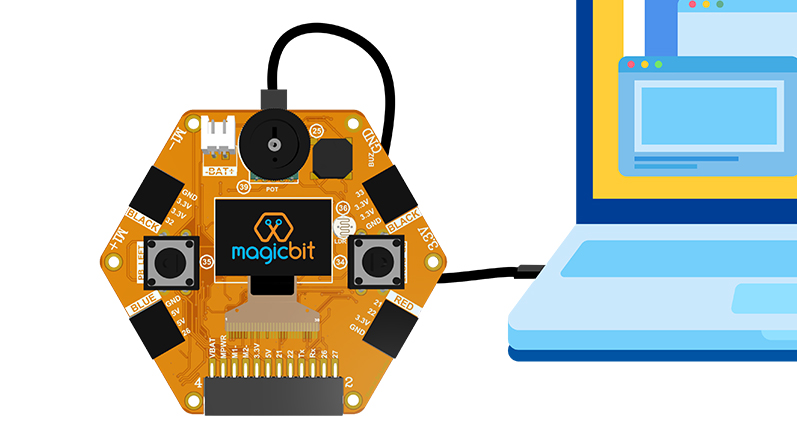
Plug your magicbit into the Computer using the USB cable provided. Your MAgicbit will automatically load the Magicbit OS.
If you bought the Magicbit recently, Magicbit OS is installed on your Magicbit from the factory. If not click here to install the Magicbit OS manually.
Magicbit OS is an all-in-one operating system that runs on Magicbit.

Magicbit OS is an all-in-one operating system that runs on Magicbit. You can switch between Magicblocks, Magiccode & test modes without the need for a computer to reprogram the board.

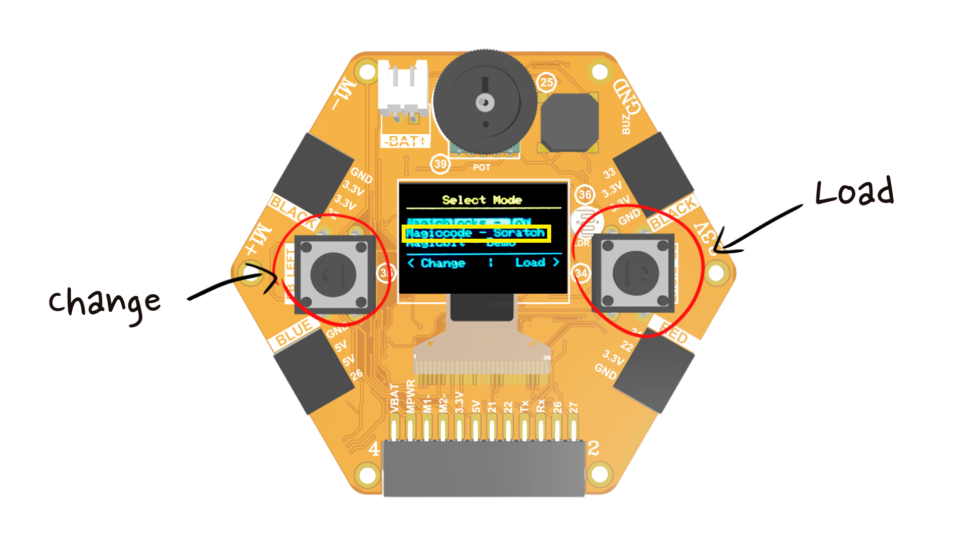
When you power up magicbit, you have 3 options to choose from. You get 10 seconds to select a mode. Otherwise your Magicbit will boot up to the mode you previously used. You can change the selection from the left push button and load the mode from the right push button.
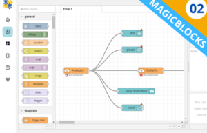
Magicblocks IoT enables you to build IoT applications with magicblocks.io platform. Find more information from www.magicblocks.io.
.
Magicode is the scratch based no-code programming platform from us.
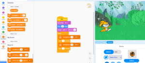
You can learn underlying theories of programming in a graphical manner using this platform. By enabling this mode, you enable Magiccode WiFi version. You can connect the magicbit to the computer and program using Magiccode, more info from here.
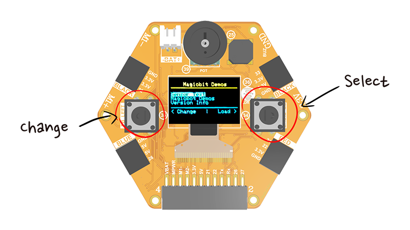 Magicbit demo >> Sensor test
Magicbit demo includes a sensor test program as well as a program to test out the Magicbot robot platform without the need of reprogramming or a computer.
 Sensor test >>
Sensor test mode could test all the sensors that come with Magicbit platform easily. . .
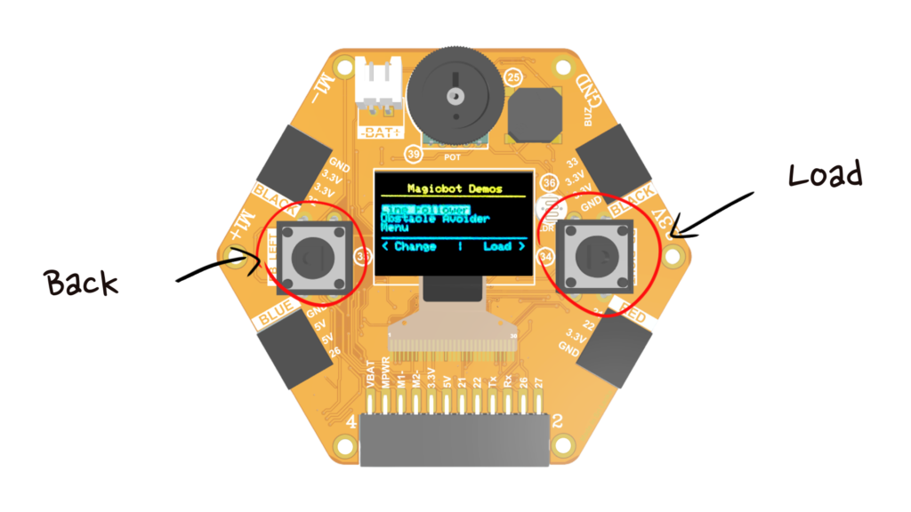 Magicbit Demo >> Magicbot demo
If you have a Magicbot robot kit, you can test run it easily. Line follower program and obstacle avoidance program can be selected from the menu.
Magicbit is a tiny computer. Any computer needs a set of instructions to work or perform a task. This is why we need to program computers or any hardware device to develop applications. The normal computers we use have operating systems which are large computer programs to help us to use the device more easily.
Since Magicbit is a tiny computer with limited capacity it can run only a small set of instructions compared to a normal computer. Programming the Magicbit will provide the instruction set to perform a specific task as defined by the Magicit user.
Programming is the way of providing instructions for computers to work. We can input instructions to computers using programs. Programming languages are used to create these instructions, and we can write the programs to perform the tasks we need from a computer. There are many popular programming languages such as C, C++, C#, Python, JavaScript, etc.

There are tools called programming IDEs (Integrated Development Environment) which provide comprehensive facilities to develop computer programs. Normally programming languages have text-based interfaces. In order to support beginners, there are visual code builders with block-based programming. In these types of programming languages or IDEs, users can simply drag and drop different blocks to create a program. Scratch is a popular visual code builder used by millions of users around the world.
Magicbit can be programmed with many text based and block based programming options. MagicCode is the Scratch version developed to support Magicbit environment. Mahgicblocks.io is another block based cloud platform developed to create IoT applications. This platform can be custom programmed using Java Script. Some of the other options available are micropython and Arduino IDE.
Although Magicbit can be programmed with multiple programming languages, it can be programmed with only one programming option at a given time.
Magicblocks
Magicblocks is an IoT(Internet of Things) platform to create IoT projects in minutes for both beginners and experts.
MagicCode
MagicCode is specially designed for kids to start learning programming with visual blocks based on Scratch3.
Arduino
Arduino is a C/C++ based language with a large community all around the world with lot of free resources.
MicroPython
This is used to program microcontrollers and robots easily with world famous python programming language.
What is Arduino?
The Arduino Integrated Development Environment is a cross-platform application that is written in functions of C and C++.
It is used to write and upload programs to Arduino compatible boards. But also with the help of third-party cores, the Arduino IDE can be used to program development boards from other manufacturers as well.
Magicbit is based on ESP32 and Arduino core because Magicbit is forked from the espressif/arduino-esp32. Therefore, to program a Magicbit with the Arduino IDE, you will have to go through the following steps.
- Install the current Arduino IDE (version 1.8 or higher is required).
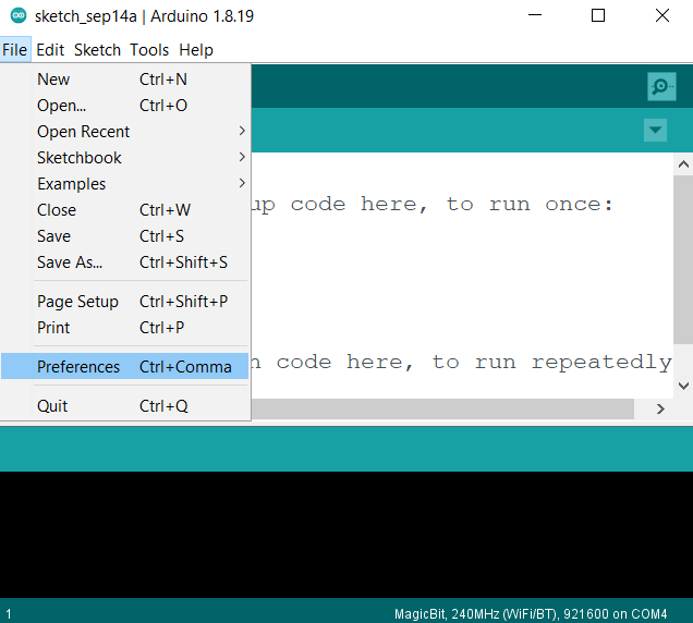
- Open the Arduino IDE and open the Preferences window from the file menu.
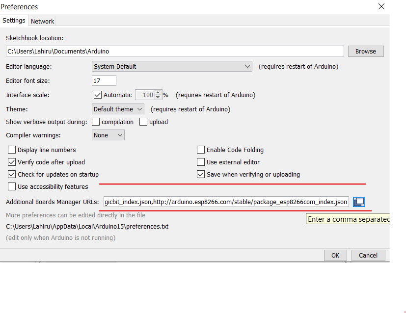
Enter the release link below into the Additional Board Manager URLs field. You can add multiple URLs, separating them with commas.
- Release link – https://github.com/magicbitlk/arduino-esp32/releases/download/Magicbit/package_magicbit_index.json
- Open Boards Manager from Tools -> Board menu
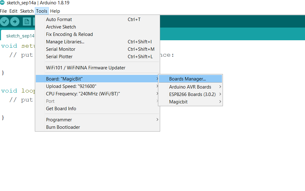 Search “magicbit” and install Magicbit platform.
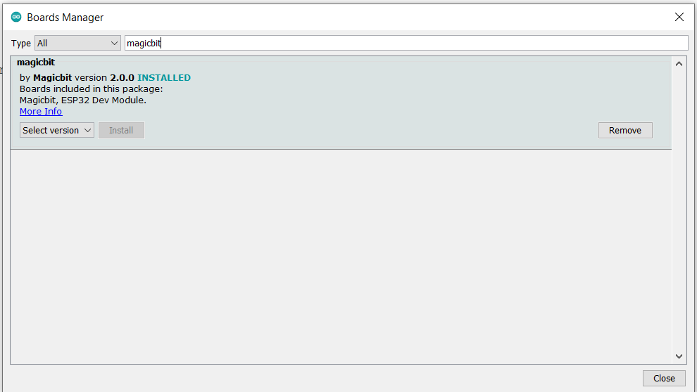
- Finally, select Magicbit from Tools -> Board menu after installation.
Magicbit has a CH340 chip as a USB-Serial converter to which the driver is already packaged with the Arduino IDE. If you have already installed the Magic OS, drivers will automatically install on your computer. Otherwise, you can Download and install (Ch-340) drivers manually by clicking the link below.
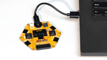 Connect Magicbit to the computer using provided USB cable.
Open the Arduino IDE and go to the Tools menu. and select the port you connected and select Board as magicbit.
- Open Arduino IDE if not opened already
- Select Magicbit from Tools ⇒ Boards
- Select port Tools ⇒ Ports
- Open Blink Example File ⇒ Examples ⇒ Basic ⇒ Blink
- Upload the code to the Magicbit using the upload button on Arduino IDE
- If the Green LED on the backside of the Magicbit is blinking, you have just begun the magic with Magicbit
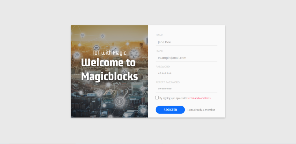
Create Magicblocks.io Account
- Go to Magicblocks website, http://magicblocks.io/
- Click on Signup Now

- Click on the Signup button after inserting your details.
- Go to the email account you provided and activate your Magicblocks account with the Activation Link.
- Follow the Activation Link that we have sent you in the email.
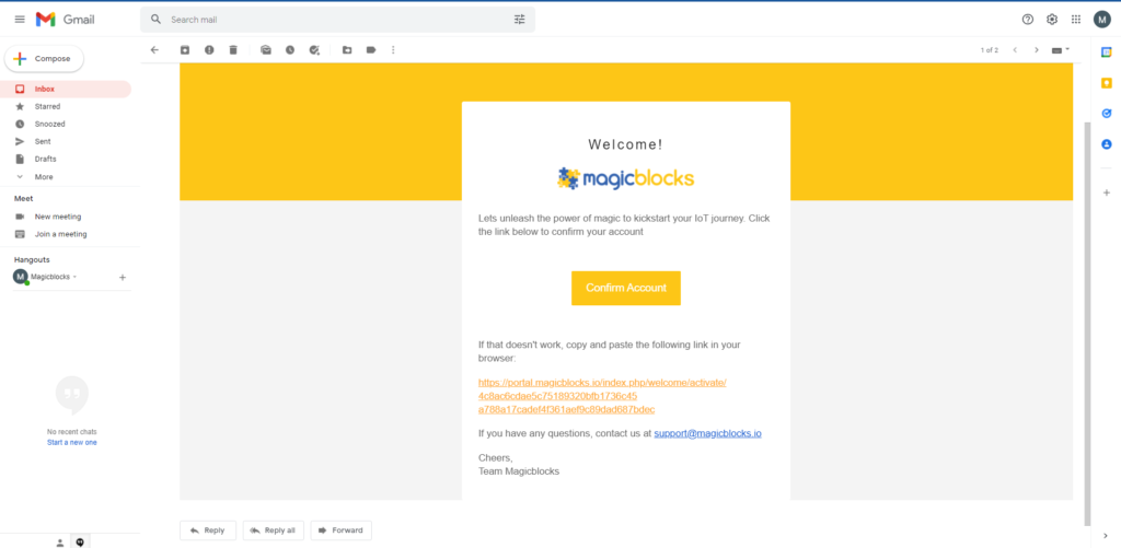
Gmail verification email
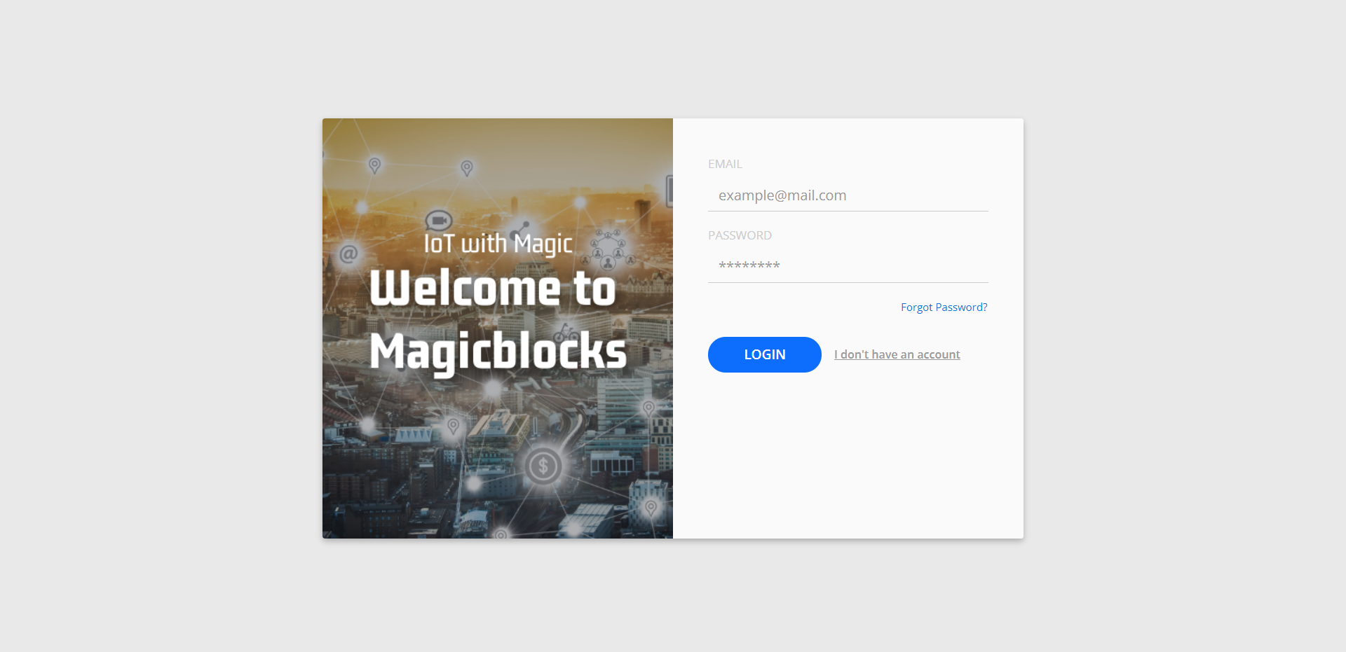
Login to Your Magicblocks.io Account
- Go to Magicblocks.io official website – magicblocks.io
- Select LOGIN.
- Provide your login details.
- Enter your email address and the Magicblocks Password and sign in to Magicblocks.
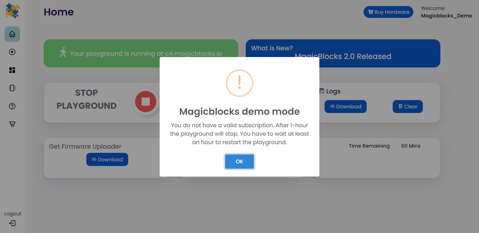
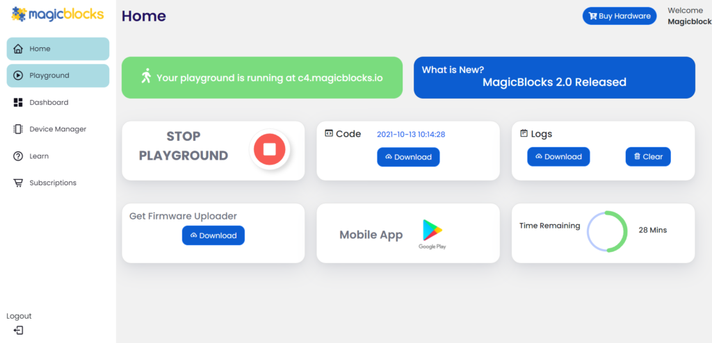
Start the Playground
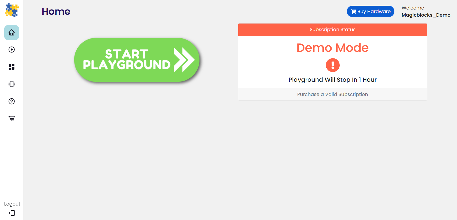
The playground is the visual programming environment based on Node-Red that has been customized for seamless integration with hardware devices to enable IoT. When you log in for the first time, your playground will not be running. If you do not have a valid subscription, you will be allowed to run the playground only for 1 hour continuously before it is automatically stopped. You will need to restart the playground manually after this 1-hour period. You can subscribe to the Standard Subscription by entering the coupon code in the Subscription tab provided with your Magicbit device. If you face any issues with the subscription, feel free to contact us at [email protected]
Create a new device
Go to Device Manager and add a new device. Set the device type as Magicbit & set the status to Active. You can use any name and description.
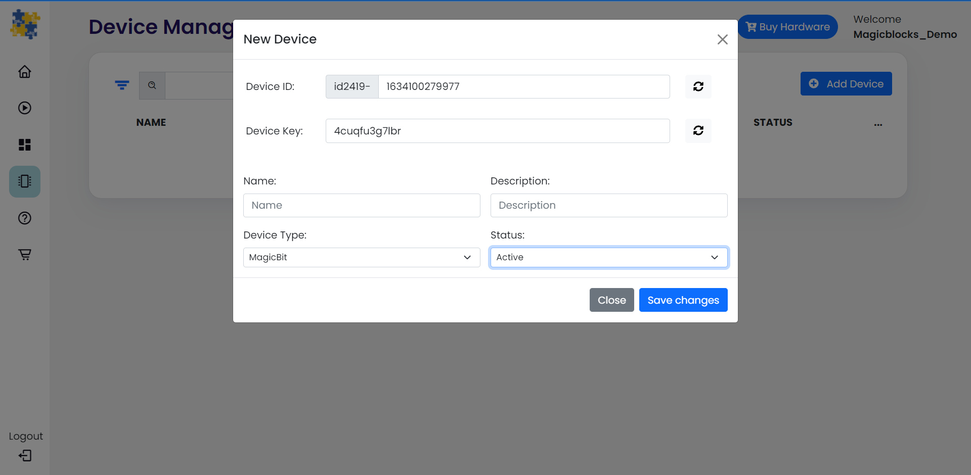
Keep this browser tab open, since you will need to copy the Device ID and the key to set up the device.
Setting up a device
- Connect Magicbit to the computer using provided USB cable.
- Connect the Magicbit to the computer. Then, click the
 button to configure the device.
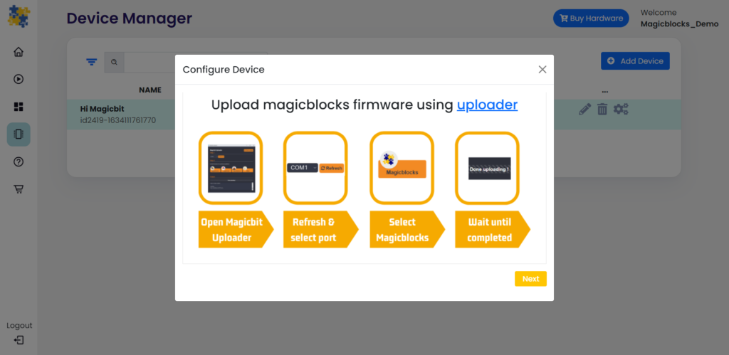
- Download the Magicbit Uploader and install it on your computer. Otherwise, you can use the Magicbit Web Uploader as well.
- Then, open the Magicbit Uploader software, install the drivers, then select your device COM port on the popup.
- Finally, install the Magicblocks firmware.
- Wait for the installation to finish. Afterwards, connect your computer to the Magicbit WiFi network.
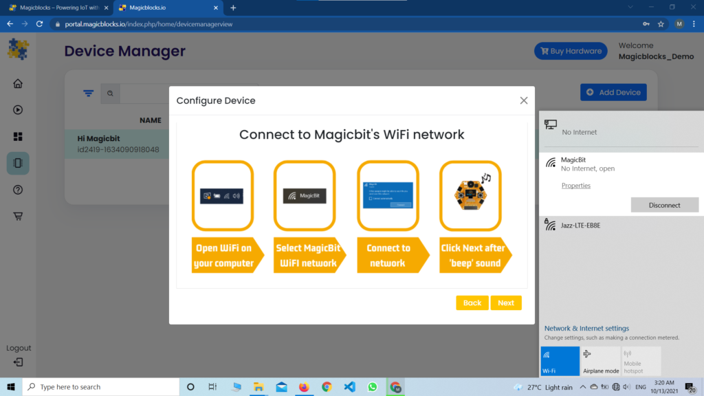
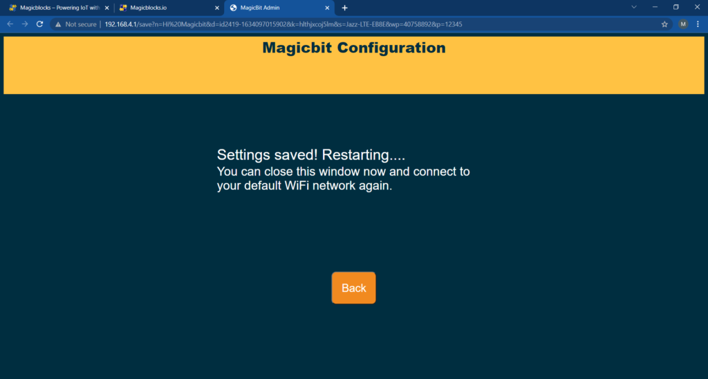
- Then, click the next button, and you will be directed to the webpage below. Once it loads, you can close the page.
- Login to Magicblocks, navigate to Device Manager and check if the Connection column indicator turns green. If it does, you can proceed to the next step. Finally, disconnect from Magicbit WiFi and reconnect to your default WiFi.
Go to the playground!
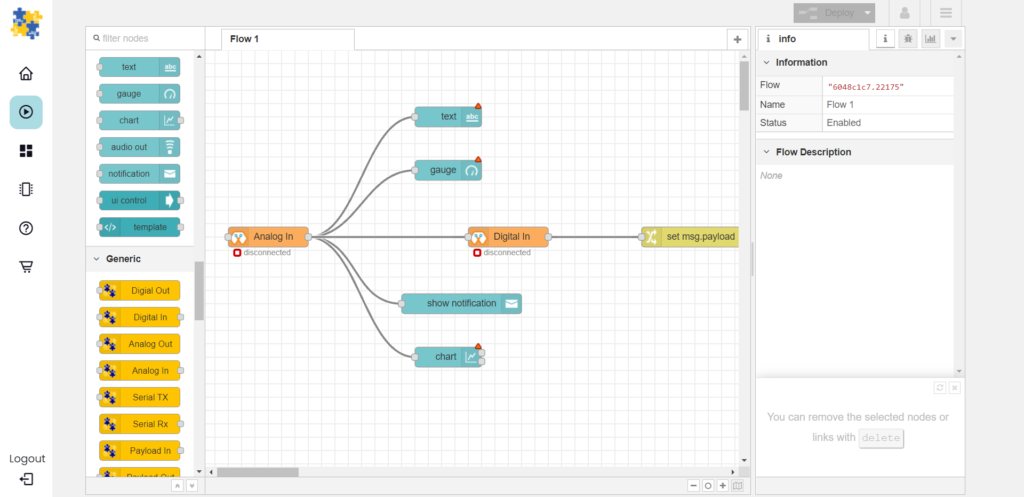
- Login to Magicblocks and click on Playground Button to open the playground.
- The playground is a hosted instance of a customized version of the open-source Node-Red application. On the left, you will find the palette where all the blocks will reside. You can drag and drop the blocks from the palette to the canvas and start rolling very quickly. Once done, click the Deploy button in the top right corner to save all your changes. In the next section, we will go through some examples covering all the relevant blocks.
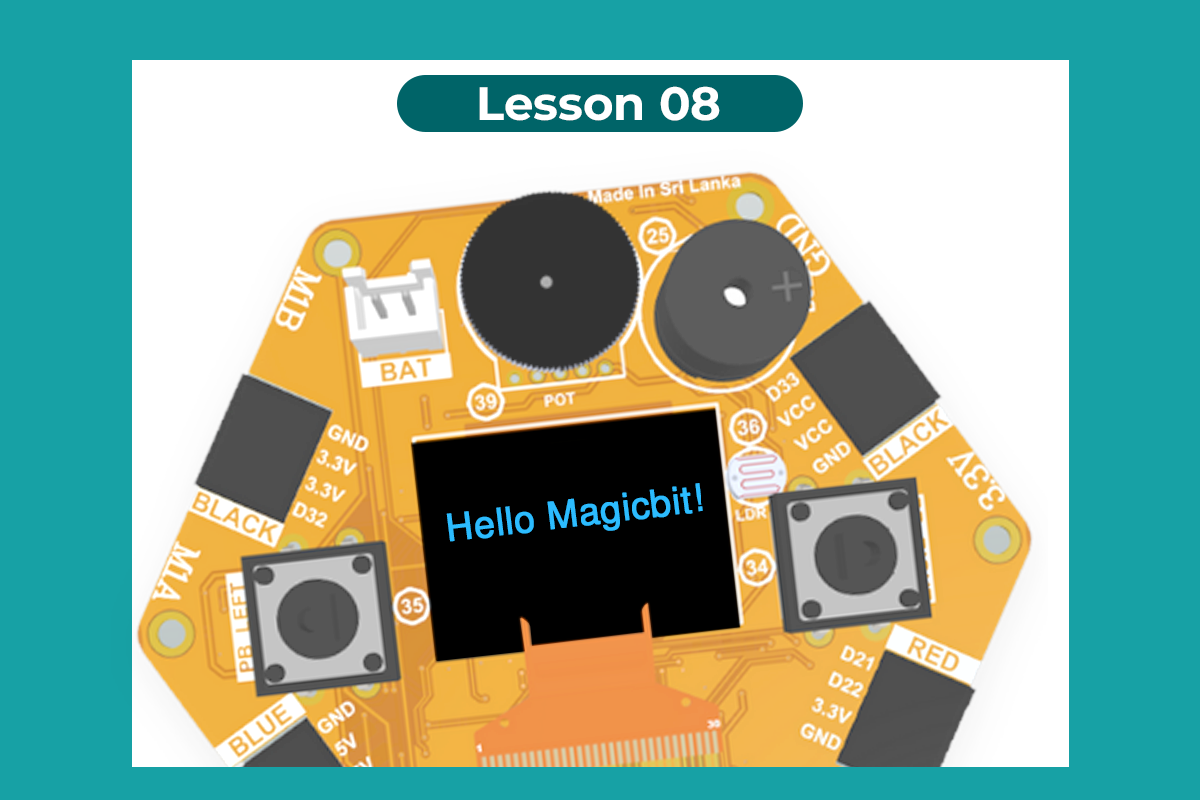
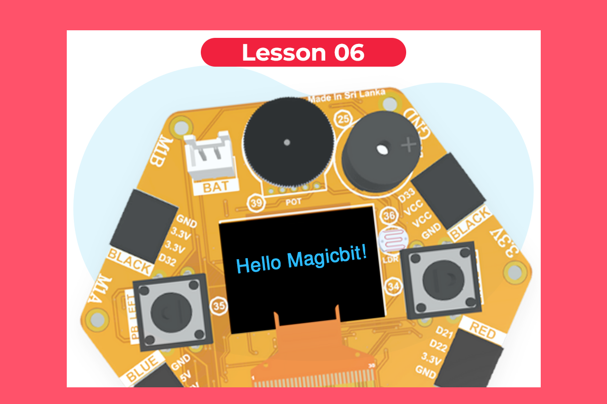
Hello Magicbit
Let’s start magic by displaying text on the Magicbit display.
- Turn on your Magicbit board that was set up in the previous section and wait for it to connect
- Open the playground
- Drag and drop the Display block, under the category Magicbit, to the playground workspace.
- Double-click on the block and select the Device ID.
- Drag and drop inject blocks under the input category and connect them to the Display block
- In one inject node set the payload type as String and type “Hello Magicbit” in the text box. You can set a topic too.
- Click Deploy
- Click the button in inject node to see the magic. You can set any text from anywhere in the world as long as your Magicbit is powered up and connected to the internet!
Introduction
MagicCode is a Scratch 3.0 based graphical programming software that makes you learn to code superfast. If you are new to the world of programming, MagicCode is one of the best companions that makes coding fun and easy. The user-friendly interface and drag and drop functionality make coding more interesting because of no need to worry about traditional programming rules. You can create your interactive games, animations, or program robots and projects with MagicCode. You can directly connect your Magicbit, Arduino, or Microbit boards with MagicCode and control generic sensors and actuators, or It also has an upload mode where you can upload your code inside boards.
Getting Started
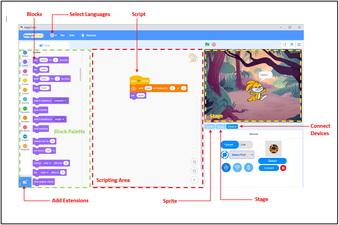
MagicCode interface and tools
- Blocks
A block is like a jigsaw puzzle piece that is used to write programs by simply dragging and dropping them below one another in the scripting area. Blocks are often easier to work with than text-based programming, as one has to memorize the commands typed and syntax errors may occur. There are ten categories of blocks: Motion, Looks, Sound, Event, Control, Sensing, Operators, Variables, List, and My Blocks. The list blocks are shown under the Variables Blocks.
- Block palette
The block palette is under the Code tab. It consists of different palettes such as Motion, Sound, and Control. Each palette has different blocks that perform functions specified by the palette name. There are other varieties of block palettes that can be loaded from the Add Extension button located at the left bottom.
- Script
A script is a program or code in MagicCode which is a collection or stack of blocks that all interlock with one another. The blocks and their order are very important, as they determine how sprites interact with each other and the backdrop. Sometimes, comments are attached to scripts to explain what certain blocks do and what the script’s purpose is. You can write multiple scripts, all of which can then run simultaneously.
- Connect Devices
Connect Devices is used to connect devices (Magicbit, Arduino, or Microbit) with MagicCode.
- Add Extensions
Add Extensions are used to add new palettes to the block palette.
- Sprite
Sprites, either user-created, uploaded, or found in the MagicCode Sprites library, are the objects that perform actions in a project. Most projects have at least one sprite as well because only sprites can move.
![]() Users can give instructions to a sprite (such as telling the sprite to move) by snapping blocks together in the script area. Clicking on the block(s) in the script area will cause the sprite to react based on the function of the block(s) clicked. Clicking on a sprite’s thumbnail in the sprite pane will bring up the script area of that sprite.
Users can give instructions to a sprite (such as telling the sprite to move) by snapping blocks together in the script area. Clicking on the block(s) in the script area will cause the sprite to react based on the function of the block(s) clicked. Clicking on a sprite’s thumbnail in the sprite pane will bring up the script area of that sprite.
The look of a sprite can also be changed by using costumes. The current costume of a sprite can be changed by clicking on the “costumes” tab and clicking on the desired costume of choice, or by using look blocks to select the sprite’s costume. New costumes for the sprite can be imported, created, and edited in the MagicCode Paint Editor.
Some sprites additionally have at least one sound. Unlike costumes, sounds are an optional field, so you can have a sprite with no sounds. The sounds tab allows you to add, delete, and edit sounds. Sounds can be played in the sound editor or with blocks that play a specific sound. Sprites (with all of their scripts, costumes, and sounds) can be exported, and then imported into another project if desired. This is achieved by right-clicking on a sprite’s thumbnail in the sprite pane and then selecting “save to local file” in the pop-up menu. A sprite can also be dragged into the backpack and dragged out into another project for transporting. However, this will not save the sprite to one’s computer.
- Stage
The stage is the background of the project where your sprites perform their actions, but it can have scripts, backdrops (costumes), and sounds, similar to a sprite, and it has its own scripts and sounds. But the stage has some restrictions on sprite functions, such as motion and size blocks.
The stage is 480 pixels wide and 360 pixels tall. All sprites have a particular position on the stage. However, no sprites can move behind the stage, and it is always at the back layer.
The Device tab is the place where you can connect your boards with MagicCode. MagicCode provides facilities to connect five boards. You can connect your Magicbit, Arduino UNO, Arduino Mega, Arduino Nano, or Microbit Boards with MagicCode. You can program your board either in live mode or Upload mode.
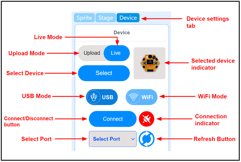
Live mode
In the Live mode, you can view the program execution effect in real-time, which facilitates the commissioning of the program.
Note
In this mode, you must keep the board connected to MagicCode. If it is disconnected, then the program cannot be executed.
Upload mode
In the Upload mode, you need to upload the compiled program to the device. After being successfully uploaded, the program can still run properly on the device when the device is disconnected from MagicCode.
Connecting Magicbit with Computer
There are two ways to connect a MagicBit to the computer.
- Wirelessly through WiFi (Useful when using magiccode for robotics and sensing applications).
- Through a USB cable from a serial connection.
WiFi Mode
If you have MagicbitOS installed in your magicbit, you can select magiccode-WiFi option to program magicbit board with magiccode. Continue from step 3 if you have magicbitOS.
1. Connect your device to the pc with a USB Connector. Alternatively, you could connect your magicbit to a 5V phone charger or a 3.7V battery too.
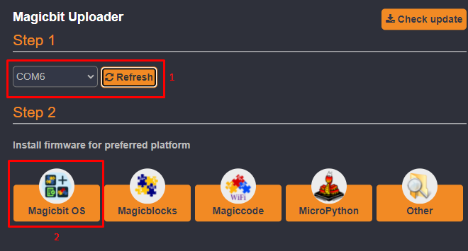
2. Upload magicbitOS firmware using magicbit uploader.
Select the correct serial port and click on magicbitOS button.
Now you can connect the board to a battery, a powerbank, or a phone charger brick. and wirelessly program the magicbit.
3. Boot from magiccode.
On the boot menu, using left key, select magiccode and press left key to load it.
4. Connect to magiccode
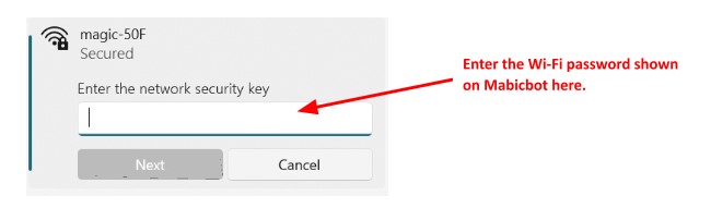
Then a SSID and a password will appear on the screen.
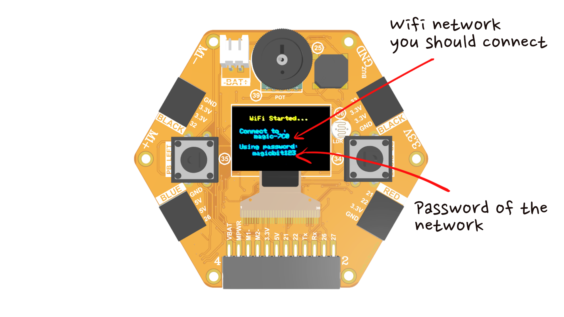
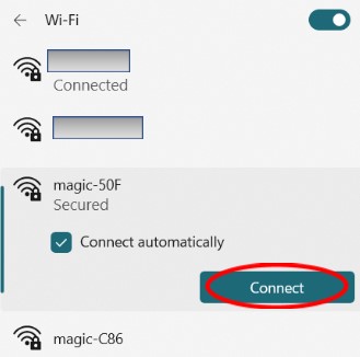
Go to wifi settings in the computer and select the wifi SSID name displayed on the Magicbit screen with the password. This will connect the board with the computer via wifi to communicate wirelessly.
5. Start building with magiccode
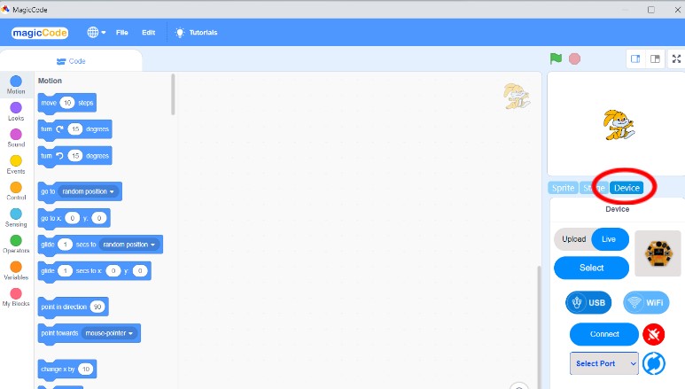
Open MagicCode software and select the devices tab.
Choose the Wi-Fi option and click on connect. This will connect the software to the board.
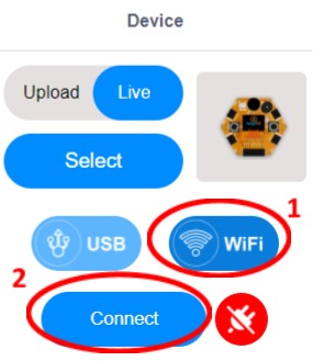
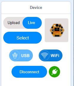
If everything works properly disconnect button will appear.
Now you can execute magiccode comands as usual.
Using USB mode.
1. Connect your device to the pc with a USB Connector.
2. Upload magicCode firmware using Magicbit Uploader
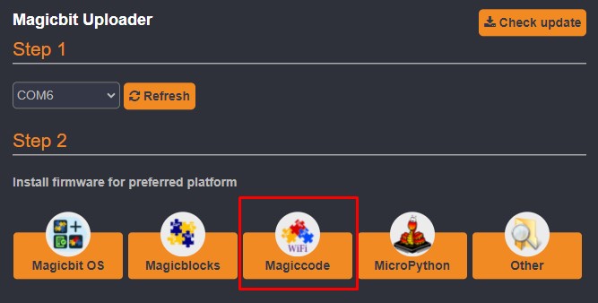
Select the correct serial port and click on magiccode icon.
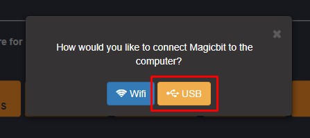
Select USB option. Then magiccode firmware will be loaded on to the magicbit.
3. Go to the Device tab at the down right corner of the MagicCode interface.
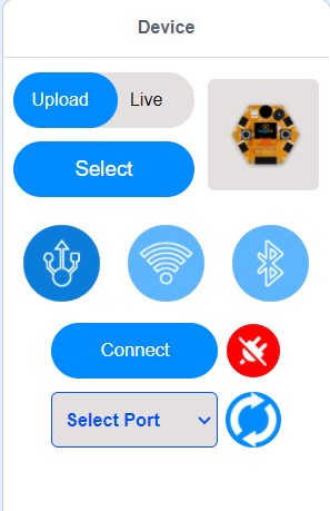
3. Select Live Mode.
4. Select your Device by clicking the Select button.
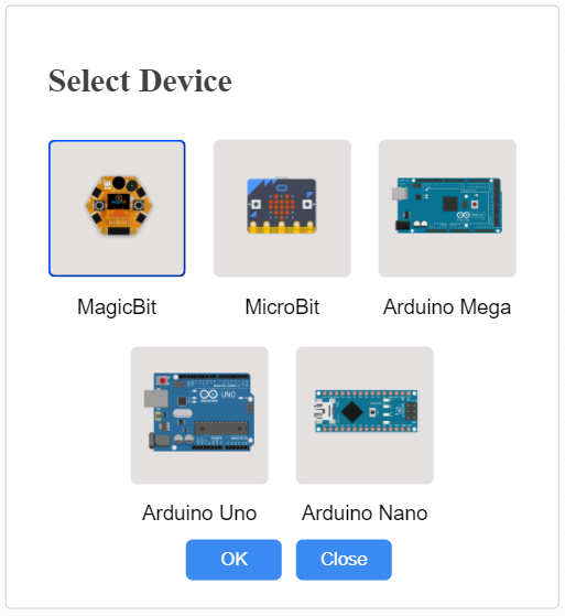
The above Devices’ library is displayed after clicking the select button and select your devices from the library.
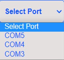
5. Select the Serial port where the device is connected.
Click on the USB mode button. Then serial port selection menu will appear.
If you don’t see any port in the select port menu, then click the refresh button. The following figure, displays the select port menu.
6. Click the connect button and connect your device to MagicCode.
After the device has connected, the “Connect” button changes to the “Disconnect” button and the icon changes.

Now you can create and execute your program with your board.
What is Micropython?
MicroPython is a lean and efficient implementation of the Python 3 programming language that includes a small subset of the Python standard library and is optimized to run on microcontrollers and in constrained environments. Learn more about MicroPython
It is very useful to use an IDE to program your Magicbit with MicroPython firmware. Thonny IDE will be introduced to you in this session. Using MicroPython and the Thonny IDE, you’ll have your first LED blinking using Micropython and thonny IDE.
Upload Micropython firmware using Magicbit Uploader
If you are starting the programing, you should have uploaded the micropython firmware to the magicbit.
- Use the magicbit web uploader or download and install Magicbit uploader offline
- Connect Magicbit to the computer
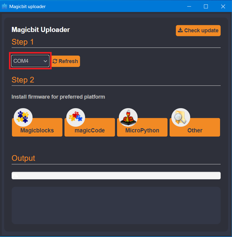
- In the web uploader, press connect button and select the correct COM port. If you are using magicbit uploader offline, open Magicbit Uploader and select your device COM Port & press connect.
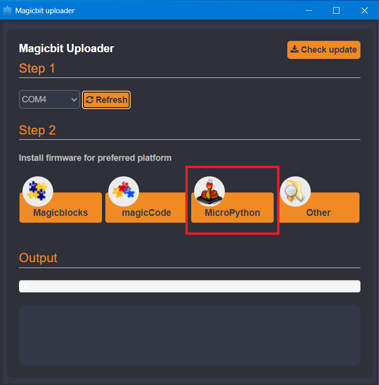
4. Install Micropython firmware
Installing Thonny IDE
- Go to https://thonny.org
- Download the version for Windows and wait a few seconds while it downloads.
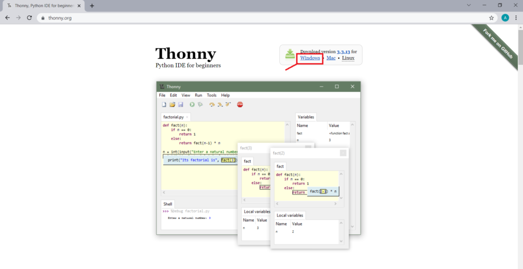
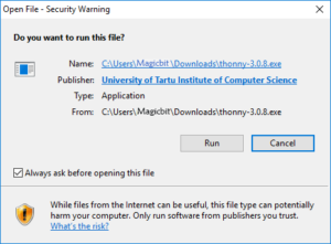
- Run the .exe file.
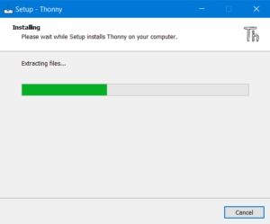
- Follow the installation wizard to complete the installation process. You just need to click “Next”.
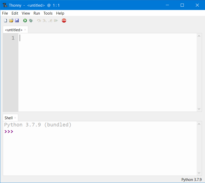
- After completing the installation, open Thonny IDE. A window as shown in the following figure should open.
Create First Project (LED Blink)
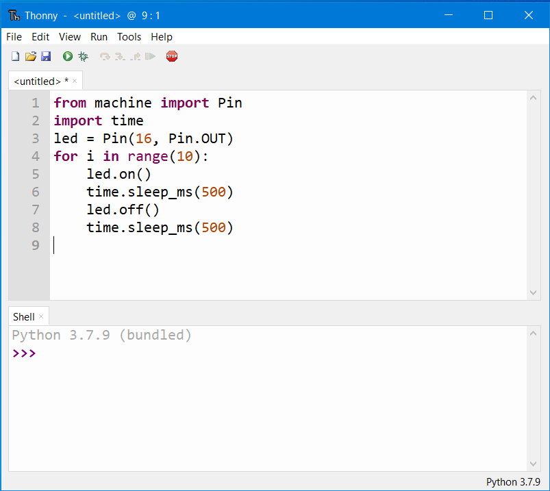
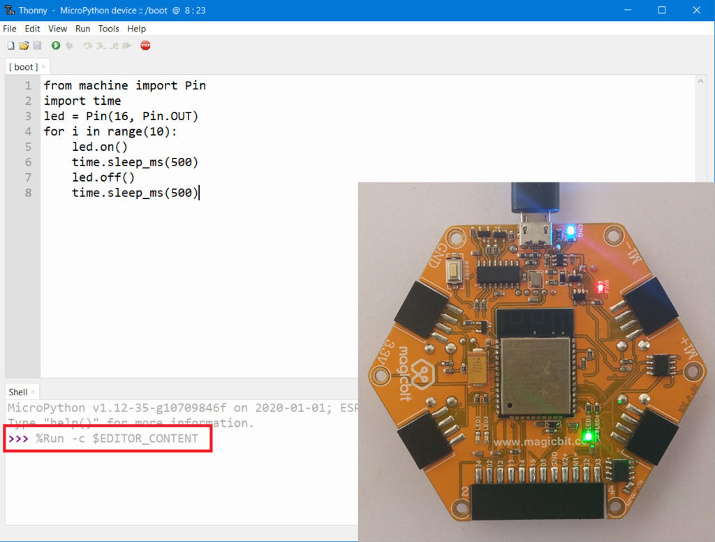
- Open Thonny IDE
- Copy – Paste following code on the editor
from machine import Pin
import time
led = Pin(16, Pin.OUT)
for i in range(10):
     led.on()
     time.sleep_ms(500)
     led.off()
     time.sleep_ms(500)
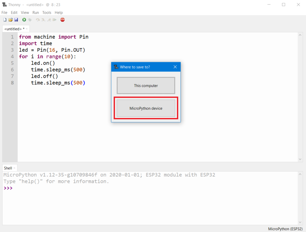
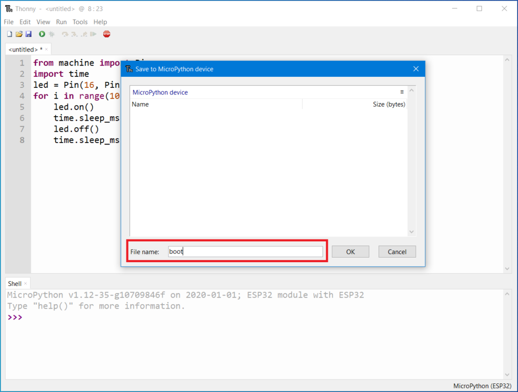
- click save as and select ‘Micropython Device’ and choose file name as ‘boot.py’
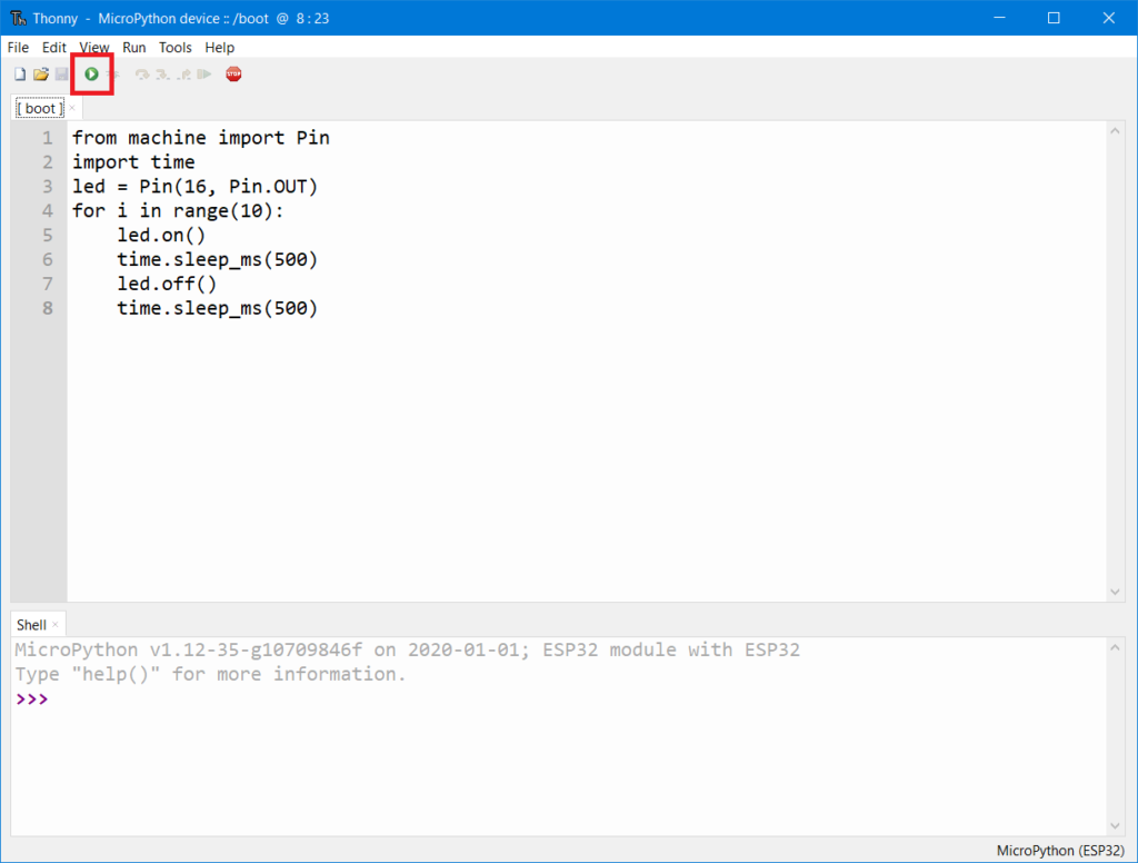
- Click Run (Green Arrow) on the IDE — If the Green LED on the backside of the Magicbit is blinking, you have just begun the magic with Magicbit
A light-emitting diode (LED) is a semiconductor light source that emits light when current flows through it.
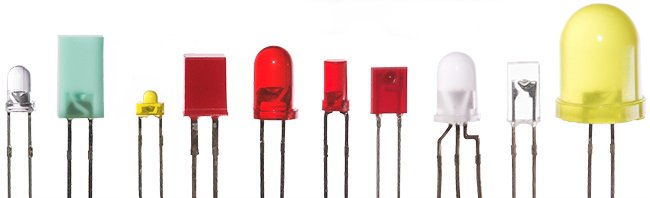
In short, LEDs are like tiny lightbulbs. However, LEDs require a lot less power to light up by comparison. They’re also more energy efficient, so they don’t tend to get hot as conventional lightbulbs do.
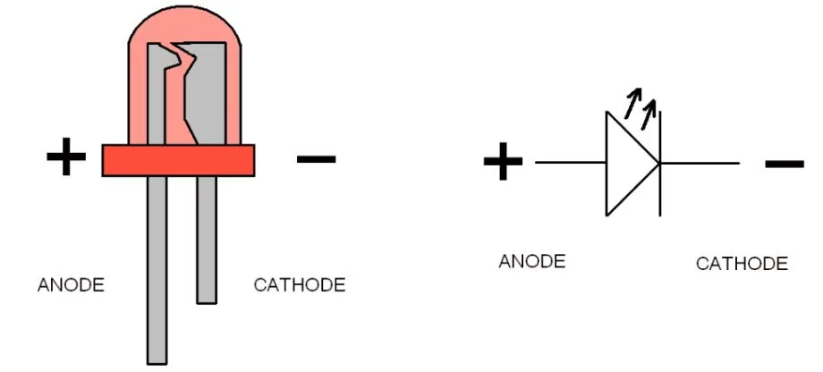
Here is the circuit symbol.
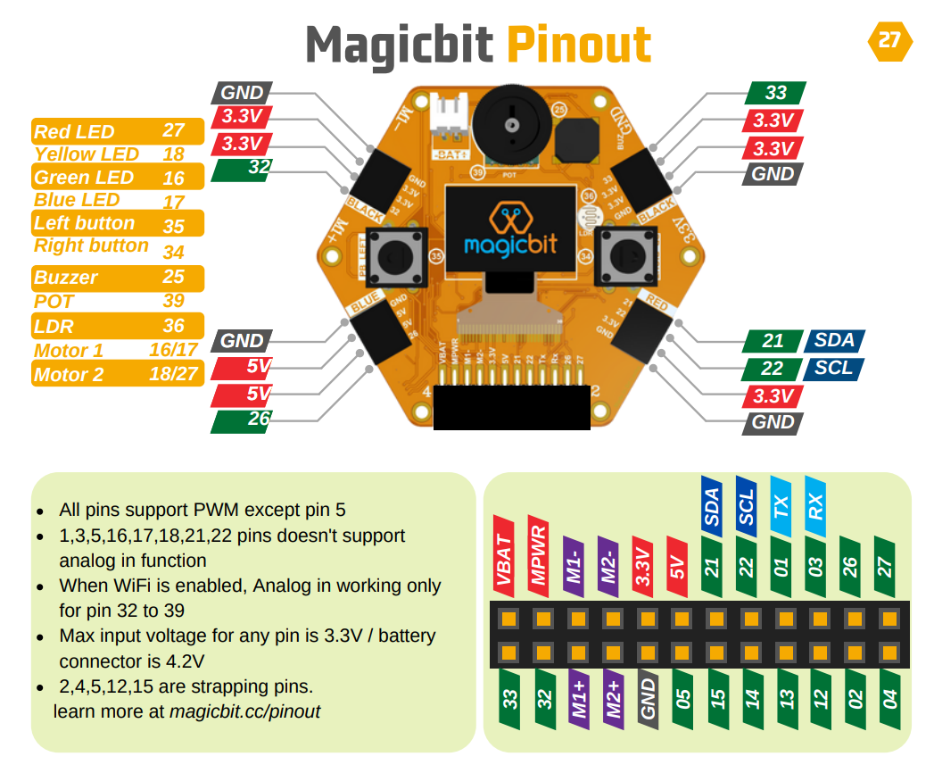
Magicbit has 4 LEDs connected to pin numbers 16, 17, 18 and 27. Setting the output state of an LED pin to HIGH, will turn on the LED and setting it to LOW will turn it off.
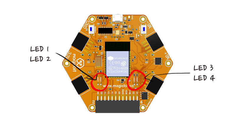 LED 1 -> Green -> pin 16
LED 2 -> Yellow -> pin 18
LED 3 -> Red -> pin 27
LED 4 -> Blue -> pin 17


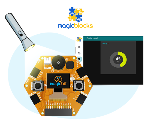
Light-dependent resistors, LDR is an electronic component that is often used in electronic circuit designs where it is necessary to detect the presence or the level of light.

Here is the circuit symbol.
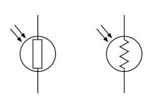
Magicbit has an inbuild LDR connected to pin 36. it gives an analog voltage input from 0 to 3.3V and it converts to a digital value of 0 to 4095.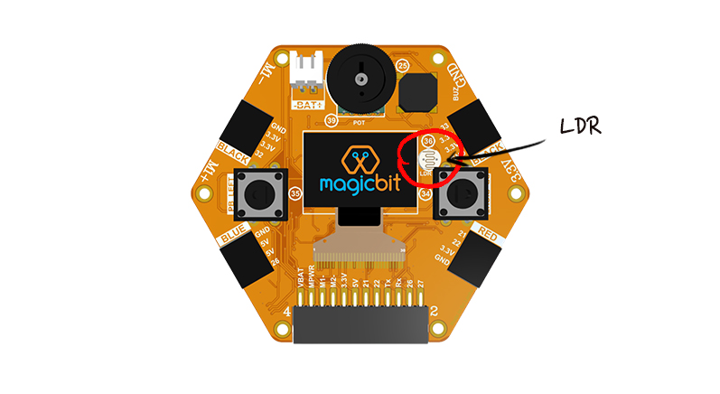
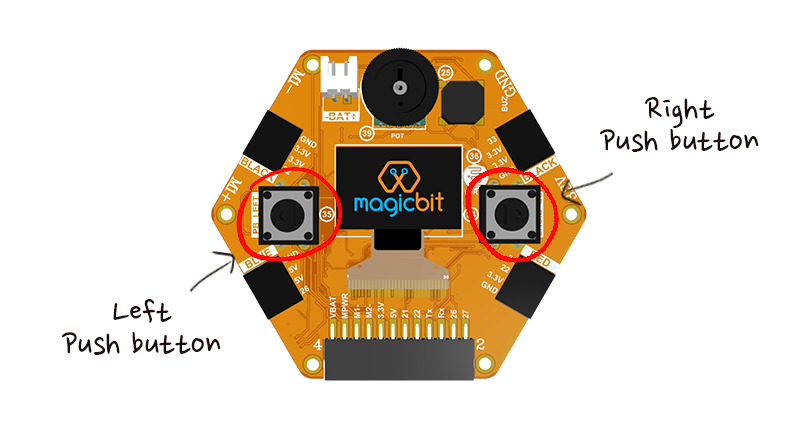
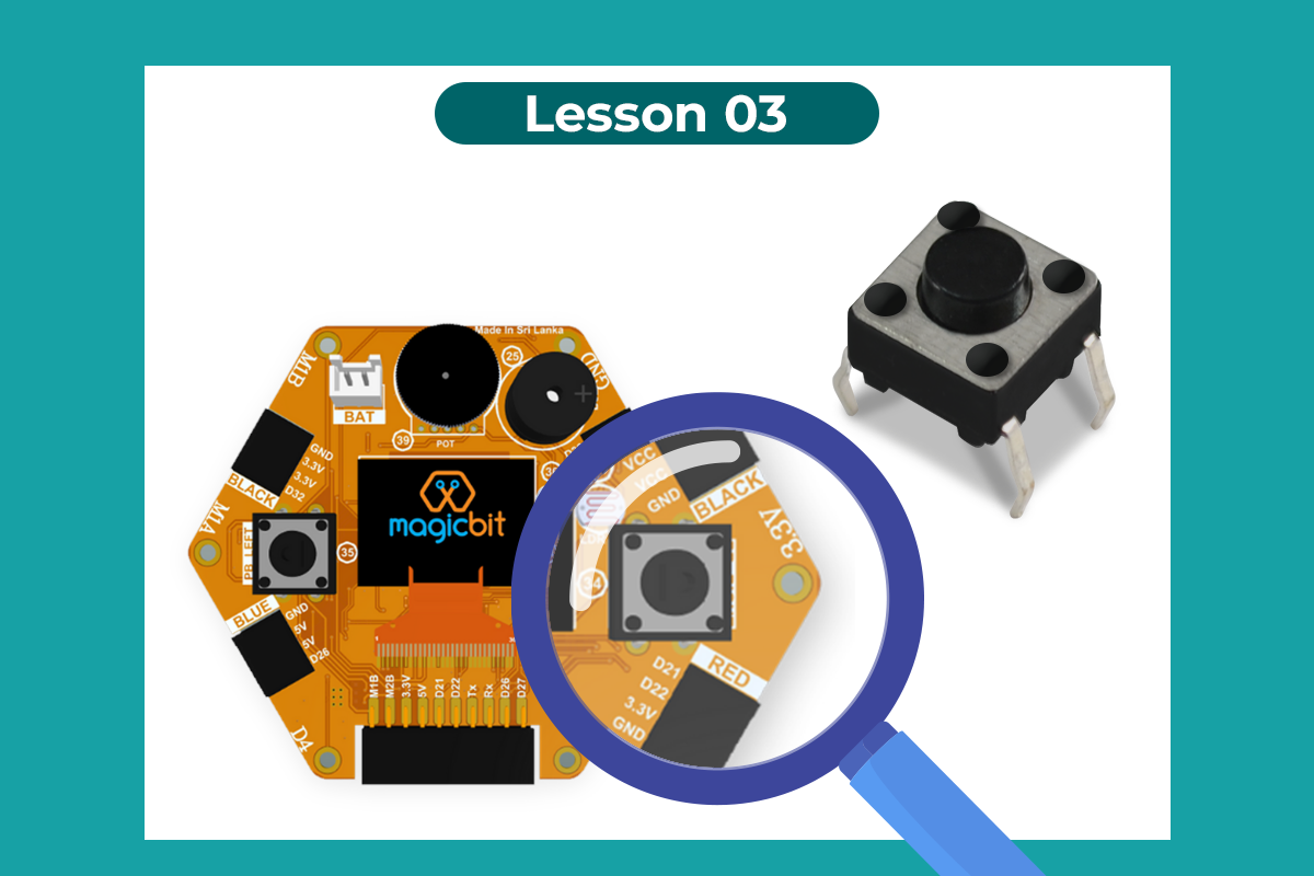
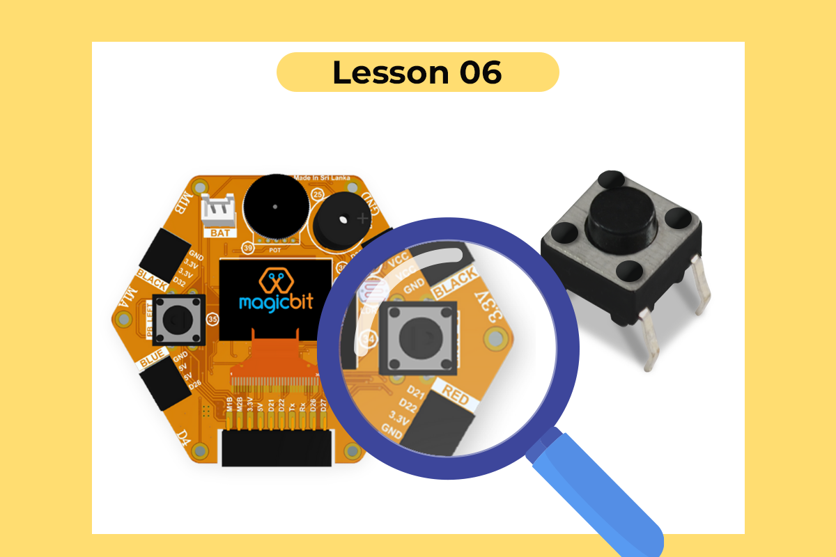
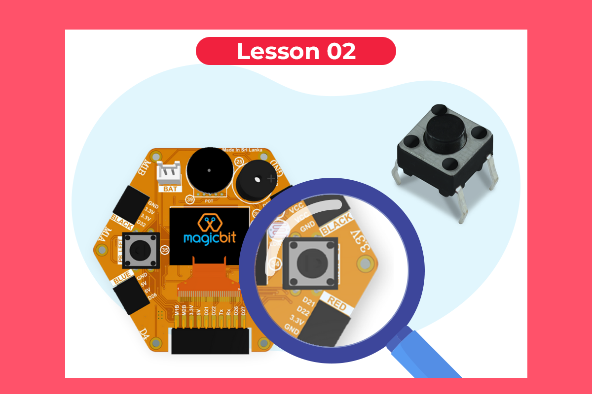
A push button switch is a mechanical device used to control an electrical circuit in which the operator manually presses a button to actuate an internal switching mechanism. They come in a variety of shapes, sizes, and configurations, depending on the design requirements.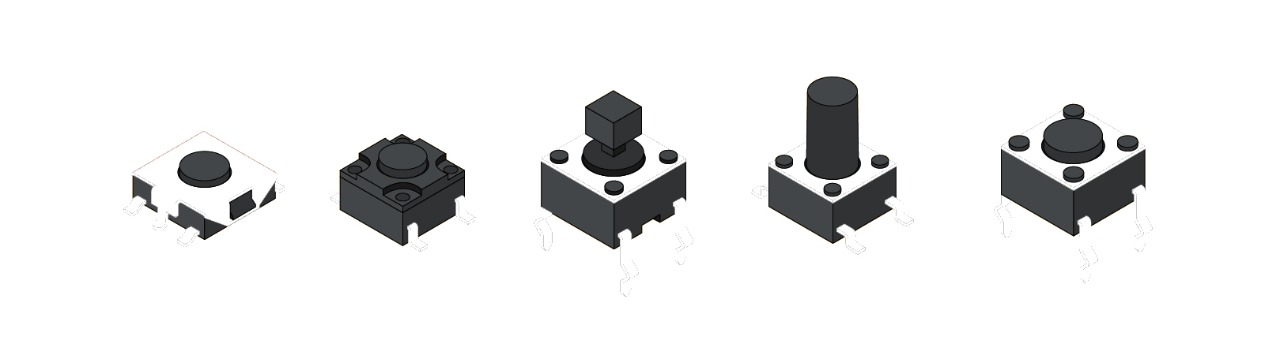
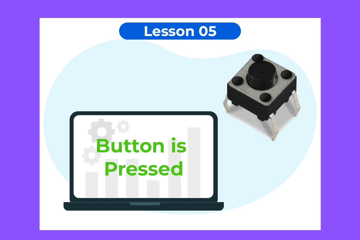
When the pushbutton is open (unpressed) there is no connection between the two legs of the pushbutton, When the button is closed (pressed), it makes a connection between its two legs.
Here is the circuit symbol.
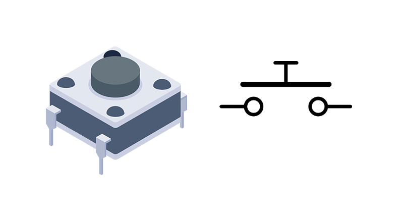
There are 2 Pushbutton on the magicbit dev board. it’s connected to the pin numbers 34 and 35.
The buzzer is also called a piezo buzzer. It is basically a tiny speaker.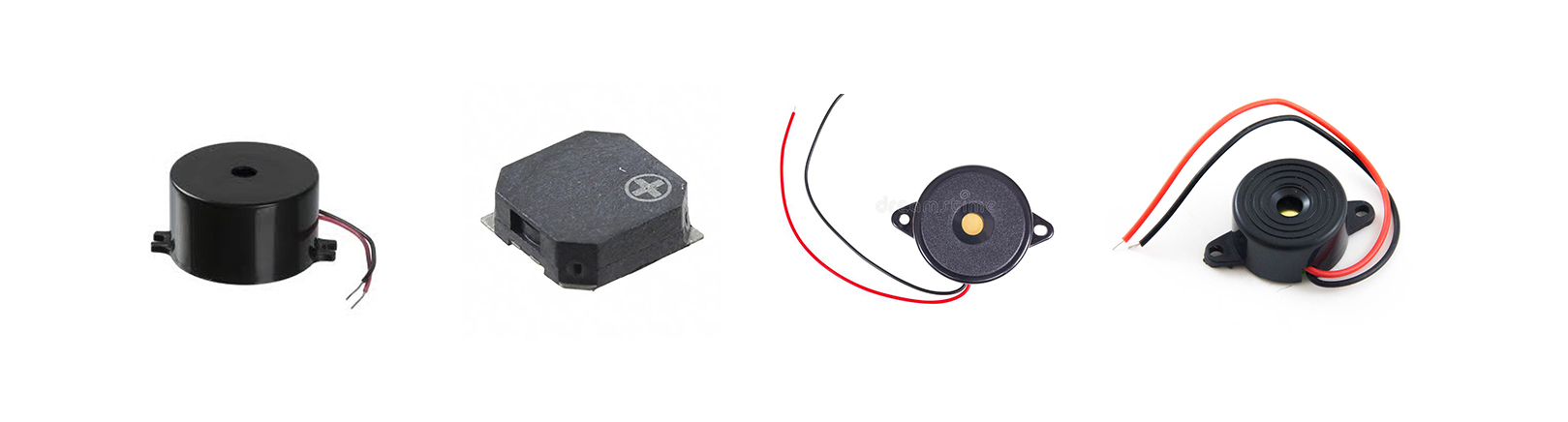
You can make it sound like a tone at a frequency you set. The buzzer produces sound based on the reverse of the piezoelectric effect.
Here is the circuit symbol
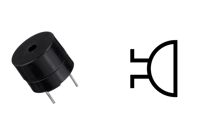
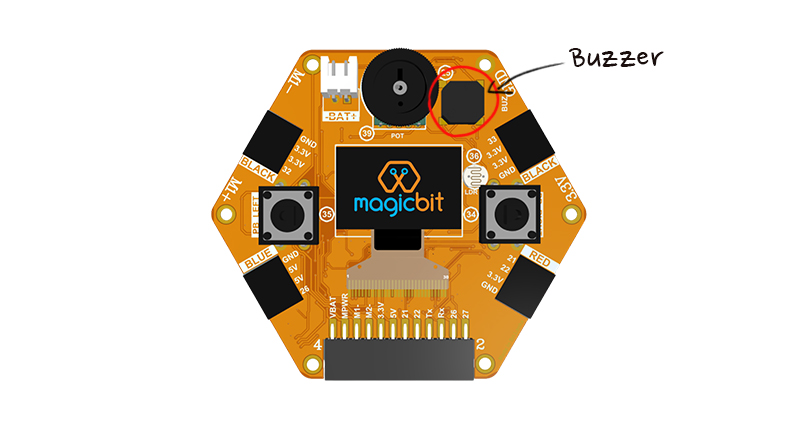
Magicbit dev board has inbuild Buzzer. it’s connected to the pin number 25.


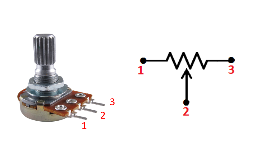
A potentiometer (also known as a pot ) is defined as a 3 terminal device. basically, the potentiometer will act as a variable resistor. When you turn the knob, the resistor will increase or decrease,
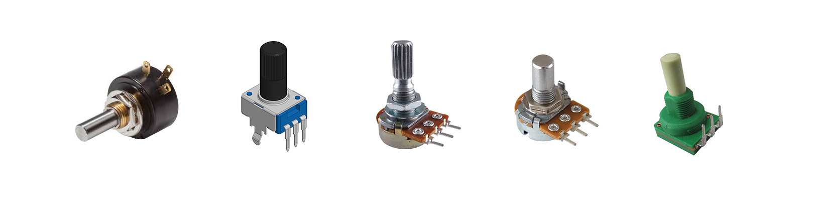
Potentiometers have a range of resistance. They can be attuned from 0 ohms to whatever maximum resistance. For example, a potentiometer of 100 kΩ can be adjusted from 0 Ω to its maximum of 100 kΩ.
Here is the circuit symbol.
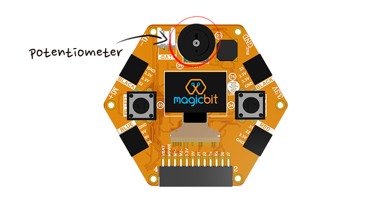
There is an inbuild potentiometer on the magicbit. which is connected to pin, D39. It generates a voltage between 0 and 3.3V according to the angle of the potentiometer.


Magicbit has a 0.96” OLED screen which can be communicated with from the I2C protocol. The display has the address, 0x3c.
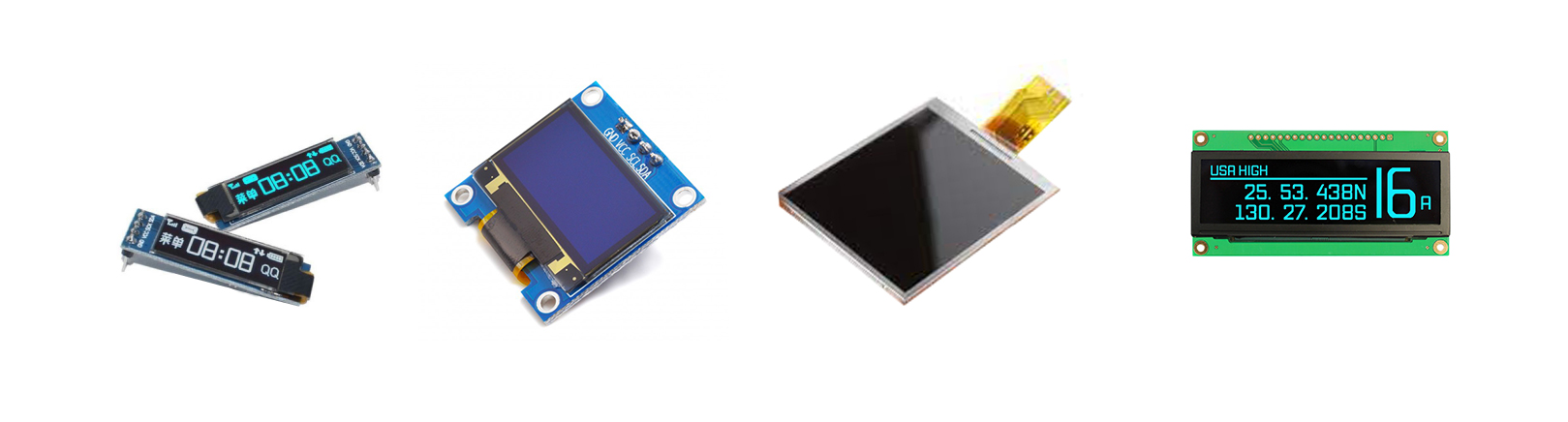
Magicbit has a 0.96” OLED screen which can be communicated with from the I2C protocol. The display has the address, 0x3c.

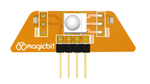
motion sensors allow you to sense motion, almost always used to detect whether a human has moved in or out of the sensors range. These sensors are commonly found in appliances and gadgets used in homes or offices. They are often referred to as PIR, “Passive Infrared”, “Pyroelectric”, or “IR motion” sensors.
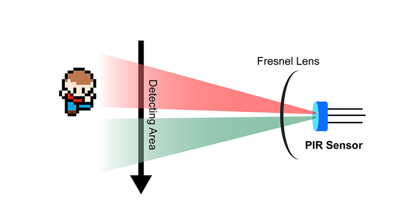
PIRs are basically made of a pyroelectric sensor (which you can see below as the round metal can with a rectangular crystal in the center), which can detect levels of infrared radiation.
Everything emits some low level radiation and the hotter something is emitted more radiation. The sensor is actually split into two halves. The two halves are wired up so that they cancel each other out. If one half sees more or less IR radiation than the other, the output will swing high or low.
An infrared sensor is similar to the object detection sensor. This sensor includes an IR LED & an IR Photodiode.The emitter is simply an IR LED (Light Emitting Diode) and the detector is simply an IR photodiode that is sensitive to IR light of the same wavelength as that emitted by the IR LED.
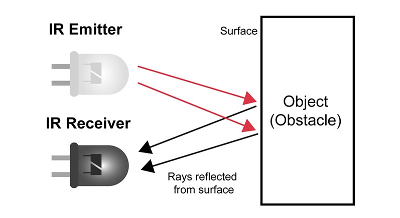
When IR light falls on the photodiode, the resistances and the output voltages will change in proportion to the magnitude of the IR light received.
proximity sensor working range is around 2-20 cm distance.
you can buy these sensors with magicbit pro. it can connect to magicbt without any wires .proximity sensor can connect pin number 32 and 33 both.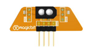
NeoPixel led is a strip of LEDs with RGB combinations. The LED was made by the Adafruit company to avoid the pins issue and complex circuitry. it can be controlled from a single pin on a microcontroller.
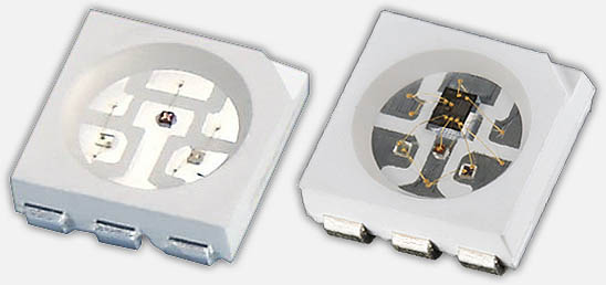
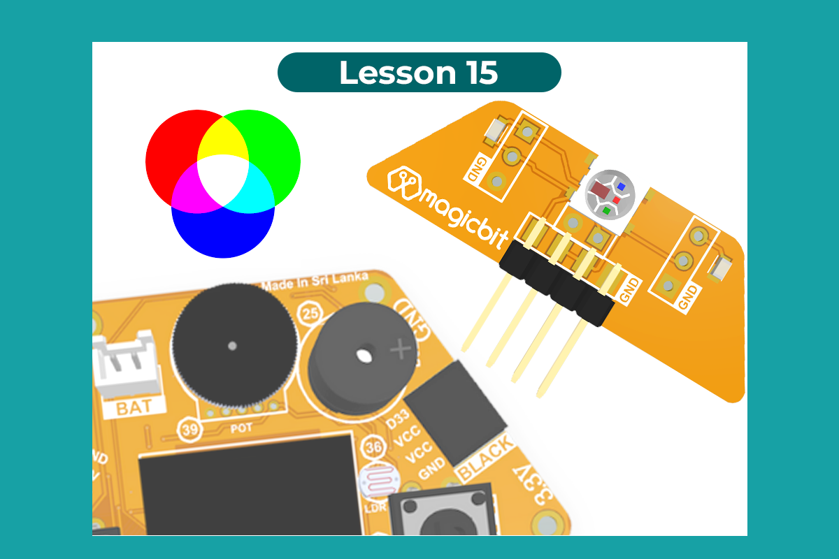
With an RGB LED you can produce almost any color. To produce other colors, you can combine the three colors in different intensities.

Here is the circuit symbol.
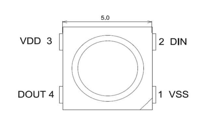
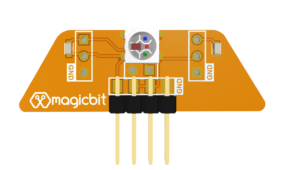
There is a pluggable RGB LED module for magicbit. you can connect it to pin number x easily.
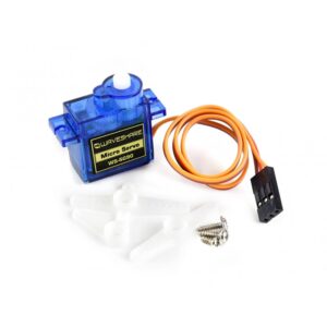
A servo motor is a kind of motor that has extremely precise rotational capabilities. A servo consists of a Motor (DC or AC), a potentiometer, gear assembly, and a controlling circuit. control circuit provides feedback on the current position of the motor shaft.

Servo motor is controlled by PWM (Pulse with Modulation) which is provided by the control wires. There is a minimum pulse, a maximum pulse and a repetition rate. Servo motor can turn 90 degree from either direction form its neutral position. The servo motor expects to see a pulse every 20 milliseconds (ms) and the length of the pulse will determine how far the motor turns. For example, a 1.5ms pulse will make the motor turn to the 90° position, such as if pulse is shorter than 1.5ms shaft moves to 0° and if it is longer than 1.5ms than it will turn the servo to 180°.
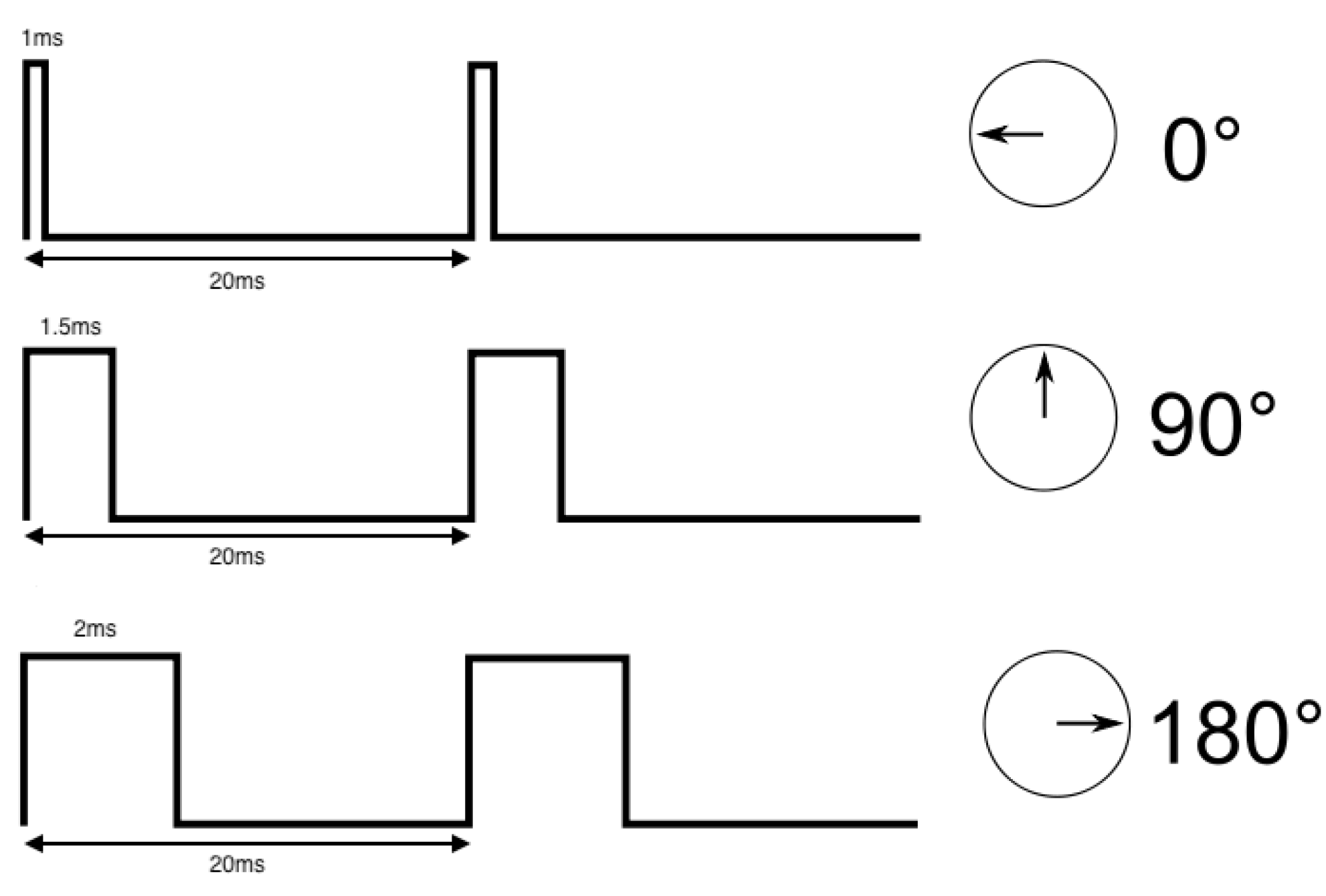
Servo motor works on PWM (Pulse width modulation) principle, means its angle of rotation is controlled by the duration of applied pulse to its Control PIN.
Servo motors are rated in kg/cm (kilogram per centimeter) most hobby servo motors are rated at 3kg/cm or 6kg/cm.
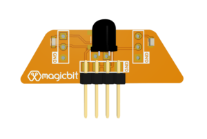
IR receiver modules are used to receive IR signals. These modules work in 3, 8 KHz frequency. When the sensor is not exposed to any light at its working frequency.

These modules have 3 pins for Vout, VDD, and Ground so it’s very easy to use them in circuits.
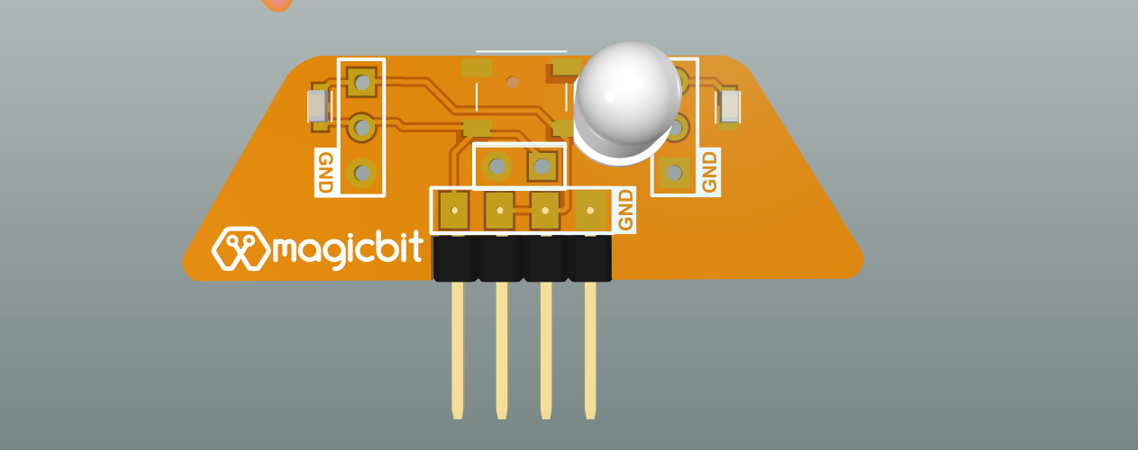
An Infrared emitter, or IR emitter, is a source of light energy in the infrared spectrum. This light-emitting diode (LED) is used to transmit infrared signals from a remote control, etc.
The output that this LED is not a usually visible spectrum. it can be seen through a smartphone camera.
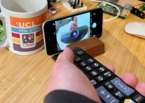 Eg- In your TV remote controller, there is an IR emitter that transmits IR signals. while pressing one button in the remote controller, observe that it emitter (LED) in the remote through your smartphone camera. you will see the LED blinks with low brightness.

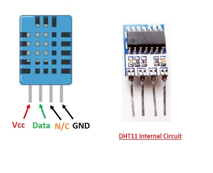
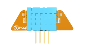
The DHT sensors are made of two parts, a capacitive humidity sensor and a thermistor.There is also a very basic chip inside that does some analog to digital conversion and spits out a digital signal with the temperature and humidity. The digital signal is fairly easy to read using any microcontroller.
- Ultra-low cost
- 3 to 5V power and I/O
- 2.5mA max current use during conversion (while requesting data)
- Good for 20-80% humidity readings with 5% accuracy
- Good for 0-50°C temperature readings ±2°C accuracy
- No more than 1 Hz sampling rate (once every second)
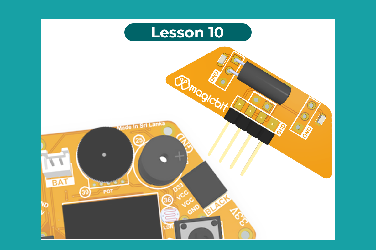
The tilt sensor is a component that can detect the tilting of an object. They are usually made by a cavity of some cylindrical and conductive free mass inside, such as a blob of mercury or rolling ball. One end of the cavity has two conductive elements. When the sensor is oriented so that that end is downwards, the mass rolls onto the poles and shorts them, acting as a switch throw.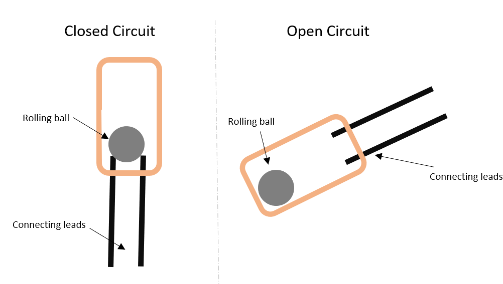

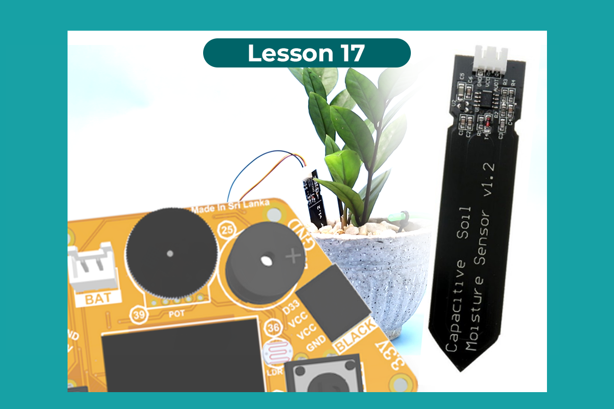
There are different types of soil moisture sensor on the market, but their working principal are all similar. All of these sensors have at least three pins: VCC, GND, and AO. The AO pin voltage changes according to the amount of moisture in the soil .
 When there is more water, the soil conducts more electricity, which means that the resistance will be less. So the moisture level will be higher. Dry soil reduces conductivity. So, when there is less water, the soil conducts less electricity, which means it has more resistance. So the moisture level will be lower.

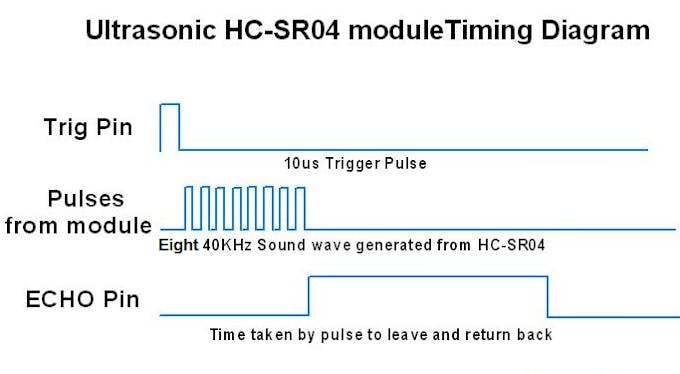
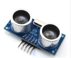
An ultrasonic sensor is an electronic device that measures the distance of a target object by emitting ultrasonic sound waves, and converts the reflected sound into an electrical signal. Ultrasonic sensors have two main components: the transmitter (which emits the sound using piezoelectric crystals) and the receiver (which encounters the sound after it has travelled to and from the target).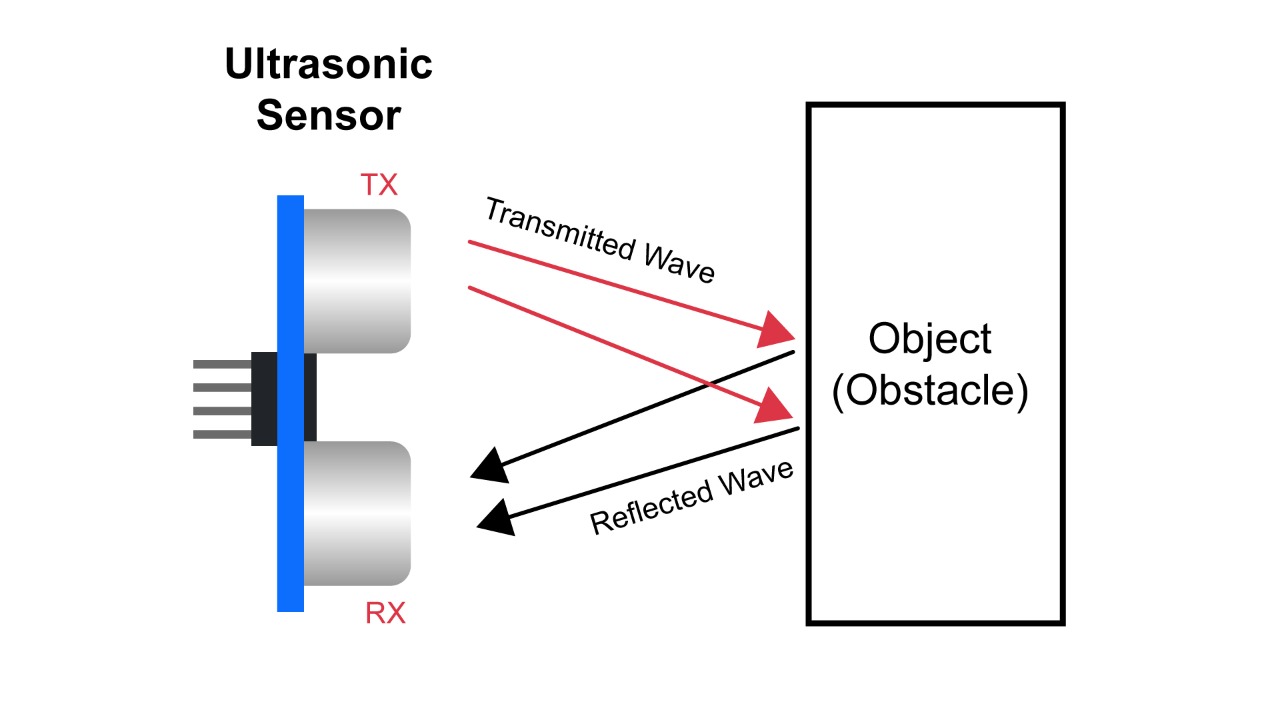 Theoretically, the distance can be calculated using the TRD (time/rate/distance) measurement formula. Since the calculated distance is the distance traveled from the ultrasonic transducer to the object—and back to the transducer—it is a two-way trip. By dividing this distance by 2, you can determine the actual distance from the transducer to the object. Ultrasonic waves travel at the speed of sound (343 m/s at 20°C).

In order to generate the ultrasound we need to set the Trigger Pin on a High State for 10 µs. That will send out an 8 cycle sonic burst which will travel at the speed sound and it will be received in the Echo Pin. The Echo Pin will output the time in microseconds the sound wave traveled.
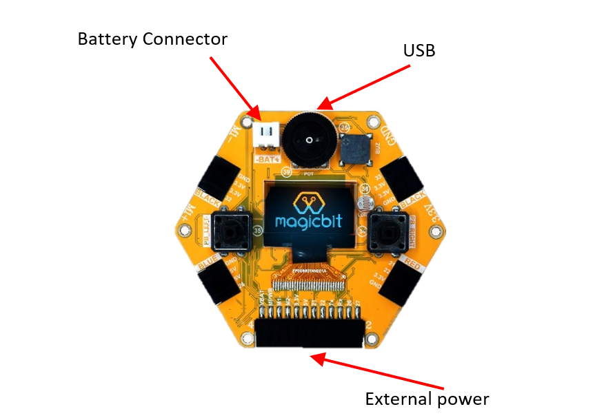
there are many ways to power magicbit dev board. you can use USB, battery, or external power to power up magicbit device. Magicbit is operated with a Voltage of 3.3V and should be handled with care to avoid any damage to user and the device.
NOTE-
- magicbit operating voltage is 3.3v but you can use a 5v supply through the USB.
- it has an inbuild battery charger module to charge li-ion 3.7v batteries.
- do not exceed the power voltage 5V limit.
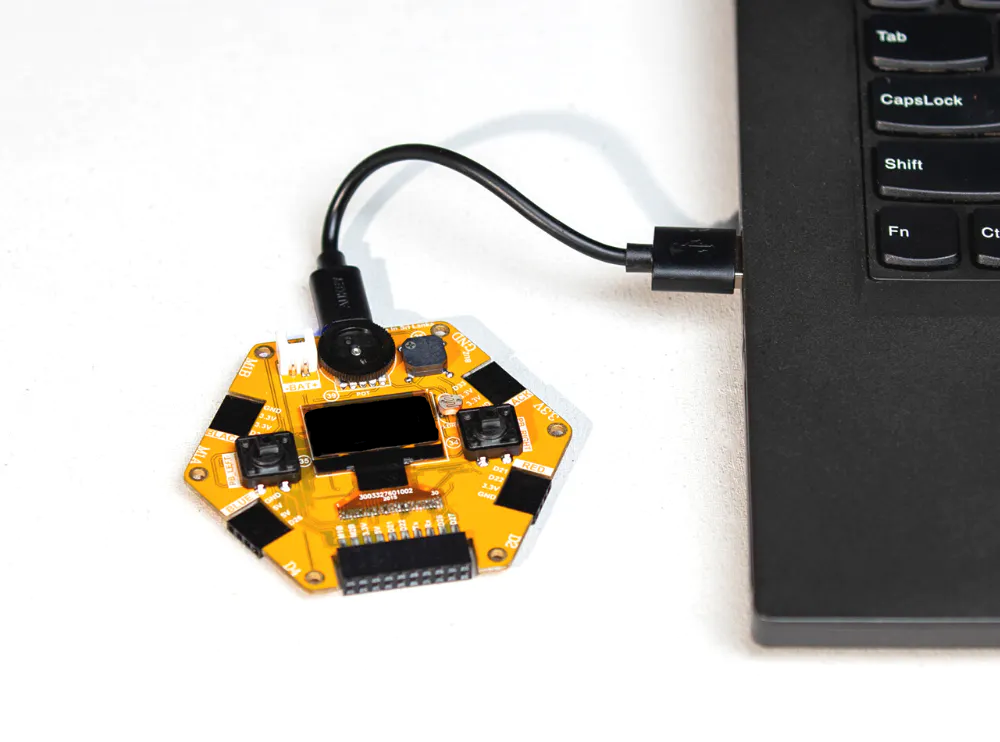
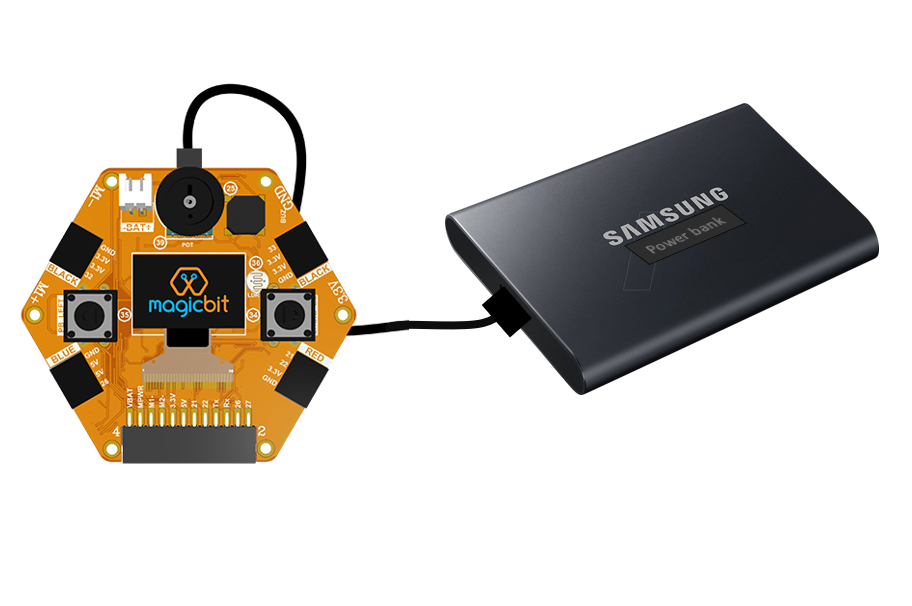
The easiest way to power your Magicbit is to use the USB cable. The magicbit includes a micro USB port which you can both supply power to the board and communication with computer.
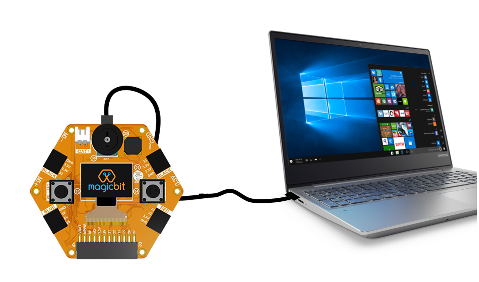 Just plug one end of the cable into your computer’s USB port or to a power bank , the other end to the USB port of the Magicbit.
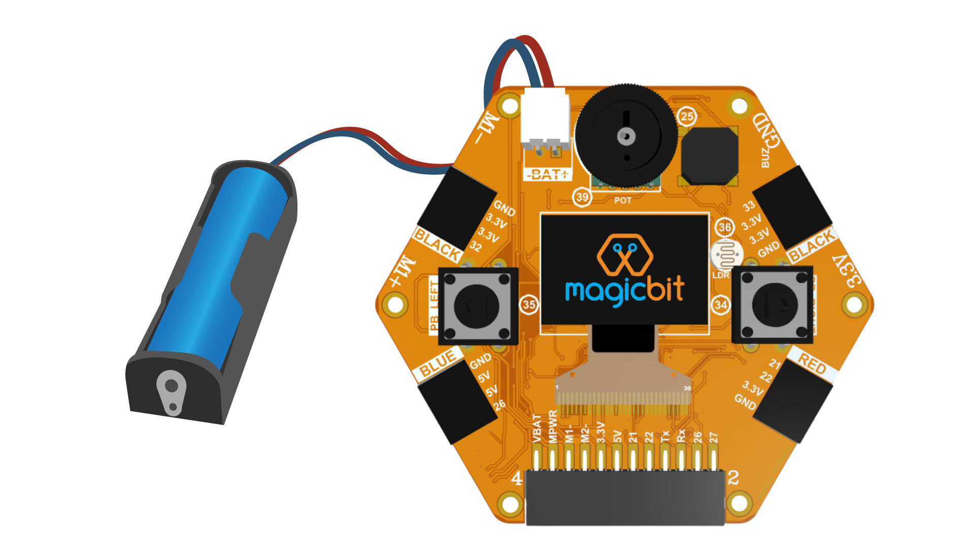
the second option is to power up the magicbit using the battery. The following batteries can be used based on your battery holder selection.
- 1x 18650 Li-ion battery
The magicbit has an inbuild battery charger. so you can charge the 3.7v li-ion 18650 battery directly from the USB port without any external charger.
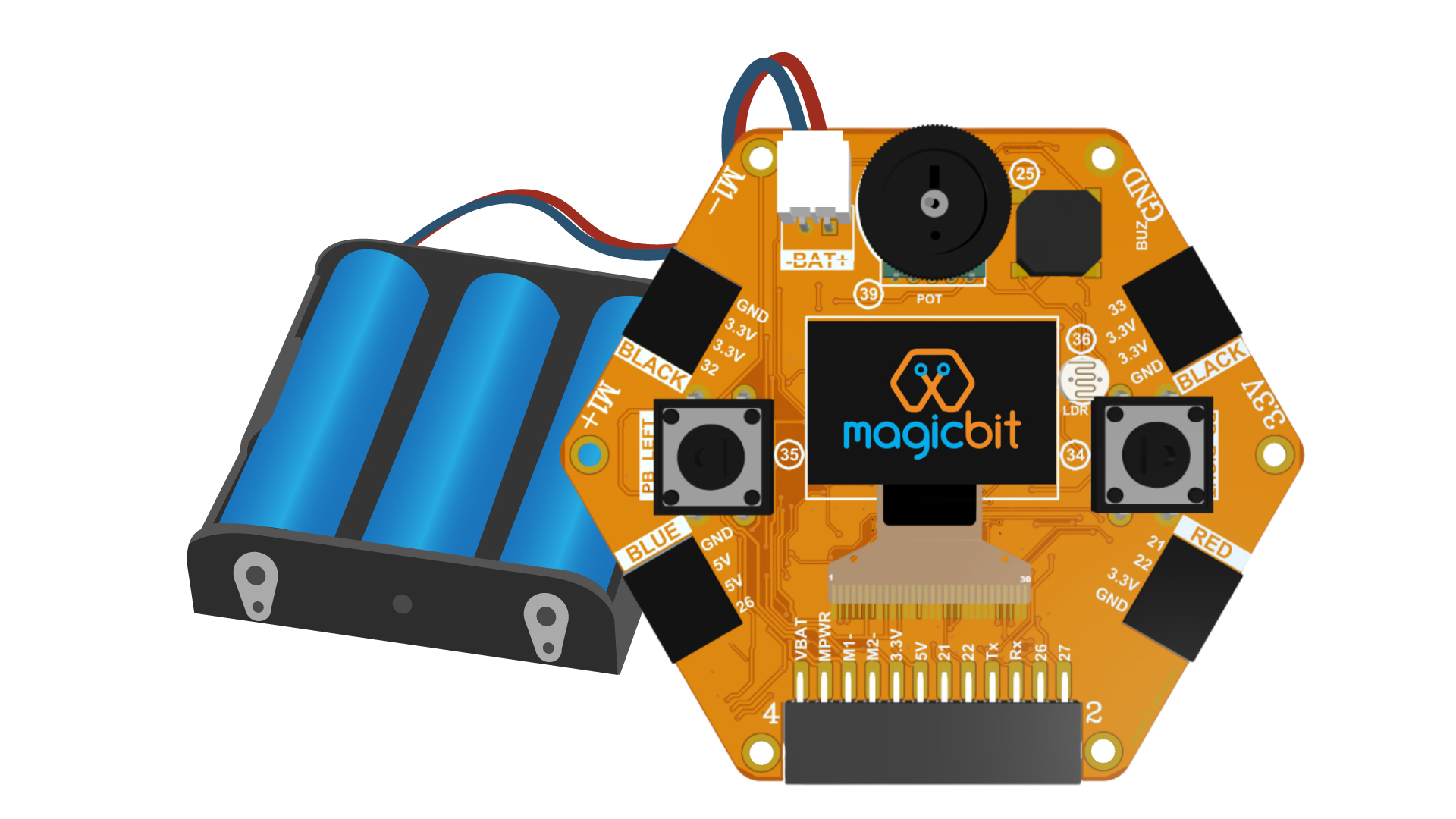
- 3x AA Alkaline Battery
- Or you can use three 1.5v AA batteries to powerup the magicbit.
The 3rd option is to connect an external 5v power supply to the VBAT pin and GND pins at bottom of the magicbit dev board.
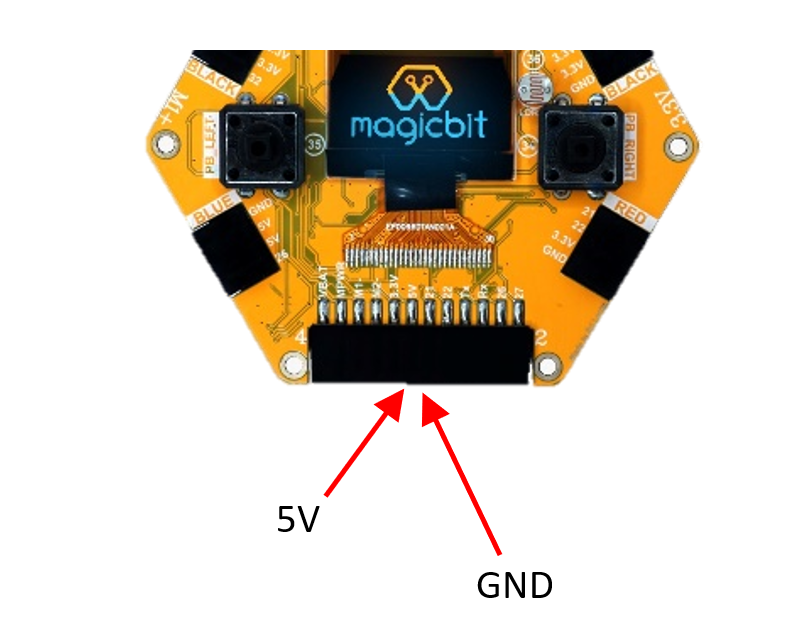
You have to be very careful when you do that. If you power your magicbit this way, you’re bypassing the onboard voltage regulator that is on board the magicbit, and therefore your magicbit has no protection against over-voltage and polarity protection.
NOTE- power supply should be 5v volts.