
Arduino Project
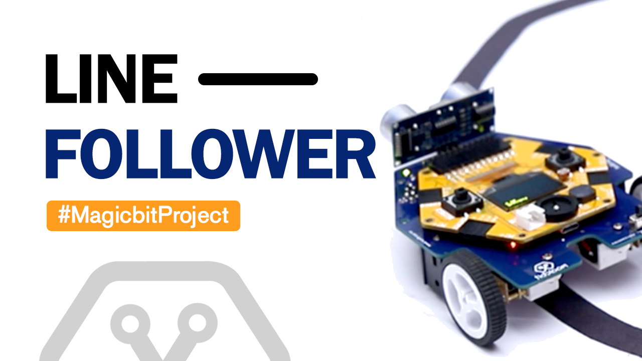
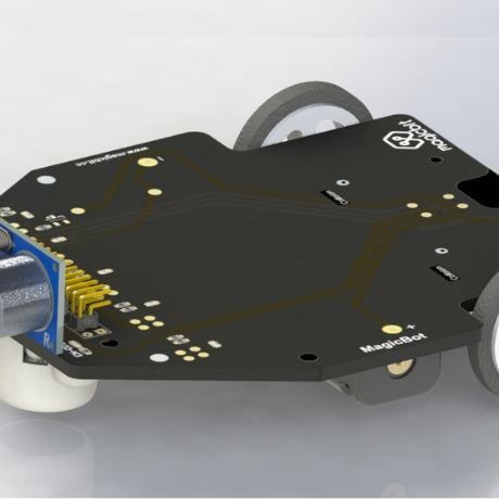
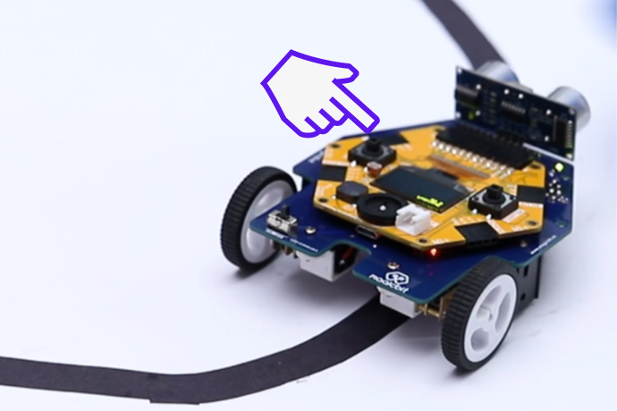
Advance Line Following Robot
Follow black line on a white surface
Components Required


Story
We will learn about how to make a line following robot using Magicbit & Magicbot platform. Keep robot on a black line on a white surface. Line width can be in the range of 15mm-35mm.
You can directly download firmware from here and upload using other option in Magicbit Uploader. Or you can continue to read for Ardunio program.
If not already installed, install QTRSensors library from Sketch->Include Library-> Search and install from Arduino library manager.
Code
#include <ESP32Servo.h>
#include <QTRSensors.h>
#include <Adafruit_GFX.h>
#include <Adafruit_SSD1306.h>

#define NUM_SENSORS 5 // number of sensors used
#define NUM_SAMPLES_PER_SENSOR 4 // average 4 analog samples per sensor reading
#define EMITTER_PIN 15 // emitter is controlled by digital pin 15
#define MOTOR1_P 16
#define MOTOR1_N 17
#define MOTOR2_P 27
#define MOTOR2_N 18
#define RIGHT_BUTTON 34
#define SENSOR1_PIN 32
#define SENSOR2_PIN 14
#define SENSOR3_PIN 26
#define SENSOR4_PIN 4
#define SENSOR5_PIN 13

Adafruit_SSD1306 display(128, 64);
QTRSensors qtra;
uint16_t sensorValues[NUM_SENSORS];
int position, proportional, power_difference, last_proportional = 0, integral = 0;

void setup() {

qtra.setTypeAnalog();
qtra.setSensorPins((const uint8_t[]) {
SENSOR1_PIN, SENSOR2_PIN, SENSOR3_PIN, SENSOR4_PIN, SENSOR5_PIN}, 5);

display.begin(SSD1306_SWITCHCAPVCC, 0x3C);

display.setTextSize(1);
display.setTextColor(WHITE);
display.setCursor(0, 0);
pinMode(MOTOR1_P, OUTPUT);
pinMode(MOTOR1_N, OUTPUT);
pinMode(MOTOR2_P, OUTPUT);
pinMode(MOTOR2_N, OUTPUT);
pinMode(EMITTER_PIN, OUTPUT);
digitalWrite(EMITTER_PIN, HIGH);
digitalWrite(MOTOR1_P, LOW);
digitalWrite(MOTOR1_N, LOW);
digitalWrite(MOTOR2_P, LOW);
digitalWrite(MOTOR2_N, LOW);
pinMode(RIGHT_BUTTON, INPUT);
Serial.begin(9600);
delay(500);
display.clearDisplay();
display.setTextSize(1);
display.println("Line Follower");
display.println();
display.println("Place robot on a black line on a white surface and press the right button");
display.display();
delay(30);
while (digitalRead(RIGHT_BUTTON))
{
//wait until button is pressed
}
display.setCursor(0, 0);
display.clearDisplay();
display.setTextSize(1);
display.println("Calibrating");
for (int i = 0; i < 34; i++) // make the calibration take about 10 seconds

{
display.print(".");
display.display();

if (i < 7)
{
analogWrite(MOTOR1_P, 0);
analogWrite(MOTOR1_N, 100);
analogWrite(MOTOR2_P, 100);
analogWrite(MOTOR2_N, 0);

}
else if (i < 21)
{
analogWrite(MOTOR1_P, 100);
analogWrite(MOTOR1_N, 0);
analogWrite(MOTOR2_P, 0);
analogWrite(MOTOR2_N, 100);
}
else
{
analogWrite(MOTOR1_P, 0);
analogWrite(MOTOR1_N, 100);
analogWrite(MOTOR2_P, 100);
analogWrite(MOTOR2_N, 0);
}
qtra.calibrate(); // reads all sensors 10 times at 2.5 ms per six sensors (i.e. ~25 ms per call)
}
analogWrite(MOTOR1_P, 0);
analogWrite(MOTOR1_N, 0);
analogWrite(MOTOR2_P, 0);
analogWrite(MOTOR2_N, 0);

display.clearDisplay();
display.setTextSize(2);
display.setCursor(0, 0);
display.println("Start Now");
display.setTextSize(1);
display.println("Press right button to start");
display.println();
display.display();
while (digitalRead(RIGHT_BUTTON));
display.clearDisplay();
display.display();
}

void loop() {

// Get the position of the line.
position = qtra.readLineBlack(sensorValues);

// The "proportional" term should be 0 when we are on the line.
proportional = ((int)position) - 2000;

// Compute the derivative (change) and integral (sum) of the
// position.
int derivative = proportional - last_proportional;
integral += proportional;

// Remember the last position.
last_proportional = proportional;

// Compute the difference between the two motor power settings,
// m1 - m2. If this is a positive number the robot will turn
// to the left. If it is a negative number, the robot will
// turn to the right, and the magnitude of the number determines
// the sharpness of the turn.

power_difference = proportional / 5 + derivative / 2 ;

// Compute the actual motor settings. We never set either motor
// to a negative value.

const int maximum = 250; // the maximum speed
if (power_difference > maximum)
power_difference = maximum;
if (power_difference < -maximum)
power_difference = -maximum;

Serial.println(power_difference);
if (power_difference > 0)
{
analogWrite(MOTOR1_P, 0);
analogWrite(MOTOR2_P, 0);
analogWrite(MOTOR1_N, maximum - power_difference);
analogWrite(MOTOR2_N, maximum);
}
else
{
analogWrite(MOTOR1_P, 0);
analogWrite(MOTOR2_P, 0);
analogWrite(MOTOR2_N, maximum + power_difference);
analogWrite(MOTOR1_N, maximum);
}
delay(10);
}