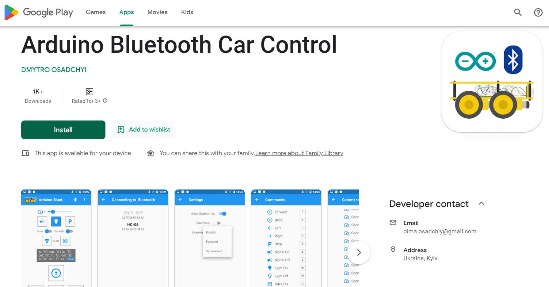
In the Arduino code, we will use a Bluetooth library to establish a connection between ESP32 and the phone. This library is already included in your Magicbit library. In the main function we search for other devices. If Magicbit is connected with some other device, then it will begin to receive data. So in the loop function we check if there any data is available. If some data is available we store that data in a variable. This data type is a characteristic data type. If we click on a vehicle controlling command button in the App, then Magicbit receives that data and generates motor outputs according to that command. In this app we can’t change the character. But in other apps we can change that key values as we like. After storing that character we compare that with defined characters of the movements. So if they are equal the robot move according to that command. The LCD part is optional. If you want you can remove it. To control the motors we use 16, 17 18 and 26 GPIO pins of ESP32. When we want to turn on the motors, we should set one pin HIGH and set the other pin LOW. To reverse the direction we have to reverse the signals. The important thing is we didn’t use additional PWM pins to control the speeds. Because we give PWM signal through high state pin. In this case we don’t use PWM theory. We only want to turn on and off the motors.
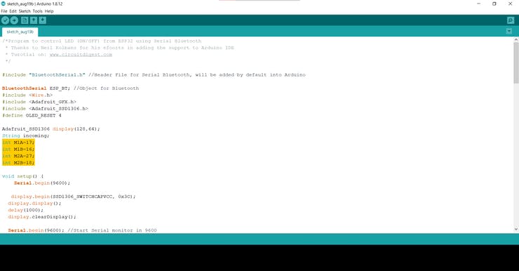
Select COM port and board type as Magicbit and upload the code. First check your motor directions are correct while running. If not then change the configuration of the pins of the motors in the code. Now you have a very simple Bluetooth controlled toy car.
Code
#include "BluetoothSerial.h" //Header File for Serial Bluetooth
BluetoothSerial ESP_BT; //Object for Bluetooth
#include <Wire.h>
#include <Adafruit_GFX.h>
#include <Adafruit_SSD1306.h>
#define OLED_RESET 4
#include <ESP32Servo.h>

Adafruit_SSD1306 display(128, 64);
String incoming;// varible store received data
int M1A = 17; // motor pins
int M1B = 16;
int M2A = 18;
int M2B = 27;

void setup() {
Serial.begin(9600);

display.begin(SSD1306_SWITCHCAPVCC, 0x3C);
display.display();
delay(1000);
display.clearDisplay();

Serial.begin(9600); //Start Serial monitor in 9600
ESP_BT.begin("MagicBot"); //Name of your Bluetooth Signal
Serial.println("Bluetooth Device is Ready to Pair");
pinMode(M1A, OUTPUT); // configure outputs
pinMode(M1B, OUTPUT);
pinMode(M2A, OUTPUT);
pinMode(M2B, OUTPUT);

}

void loop() {

if (ESP_BT.available()) //Check if we receive anything from Bluetooth
{
incoming = char(ESP_BT.read()); //Read what we received
}
Serial.println(incoming);
if (incoming == "F") { // forward
Serial.println("Forward");
Display("Forward");
Forward();
}
else if (incoming == "B") { // reverse
Serial.println("Reverse");
Display("Reverse");
Backward();
}
else if (incoming == "R") { //turn right
Serial.println("Right");
Display("Right");
Right();
}
else if (incoming == "L") { // turn left
Serial.println("Left");
Display("Left");
Left();
}
else if (incoming == "O") { // turn left
Serial.println("Horn");
Display("Horn");
tone(25,500,500);
}


else {
Stop();

Display("Stop");
}
delay(20);
}

void Forward() {

digitalWrite(M1A, HIGH);
digitalWrite(M1B, LOW);
digitalWrite(M2A, HIGH);
digitalWrite(M2B, LOW);

}

void Backward() {

digitalWrite(M1B, HIGH);
digitalWrite(M1A, LOW);
digitalWrite(M2B, HIGH);
digitalWrite(M2A, LOW);

}
void Right() {

digitalWrite(M1A, HIGH);
digitalWrite(M1B, LOW);
digitalWrite(M2B, LOW);
digitalWrite(M2A, LOW);

}
void Left() {

digitalWrite(M1B, LOW);
digitalWrite(M1A, LOW);
digitalWrite(M2A, HIGH);
digitalWrite(M2B, LOW);

}

void Stop() {
digitalWrite(M1B, LOW);
digitalWrite(M1A, LOW);
digitalWrite(M2A, LOW);
digitalWrite(M2B, LOW);

}


void Display(String commond) { // display data
display.clearDisplay();

display.setTextSize(3); // Normal 1:1 pixel scale
display.setTextColor(WHITE); // Draw white text
display.setCursor(0, 20); // Start at top-left corner
display.println(commond);
display.display();

}
If you need help or couldn’t understand a step be sure to check out our youtube video by clicking here: Youtube Video

