Use Push Buttons on your Magicbit [Magicblocks]
Use the Push Buttons on your Magicbit using Magicblocks
Components Required
Story
Hello and Welcome, This short tutorial will teach you how to work an input type button with a Magicbit using Magicblocks.
There are 1 main method of achieving this goal;
- By using Dashboard Text.
First, log into your Magicblocks account,
Magicblocks is easy visual programming software to program your magic bit. Anyone can program their microcontroller by using magicblocks.io and there is no need for programming knowledge. You can sign up for free.
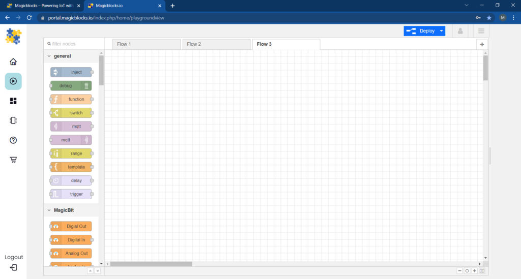
Start and Open the Playground.
Next, make sure your Magicbit is connected to the internet and plugged in, and also linked to your account through Device Manager.
All Done? Then scroll down to Method 1
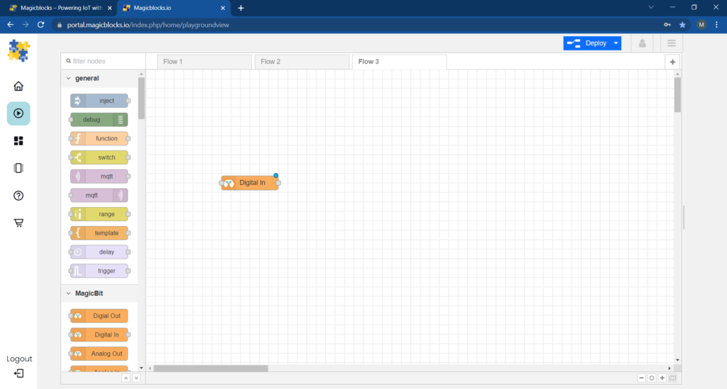
Setting Up the Digital In Block
1. Drag & drop the Digital In block from the input nodes section on the left of the screen to the Flow.
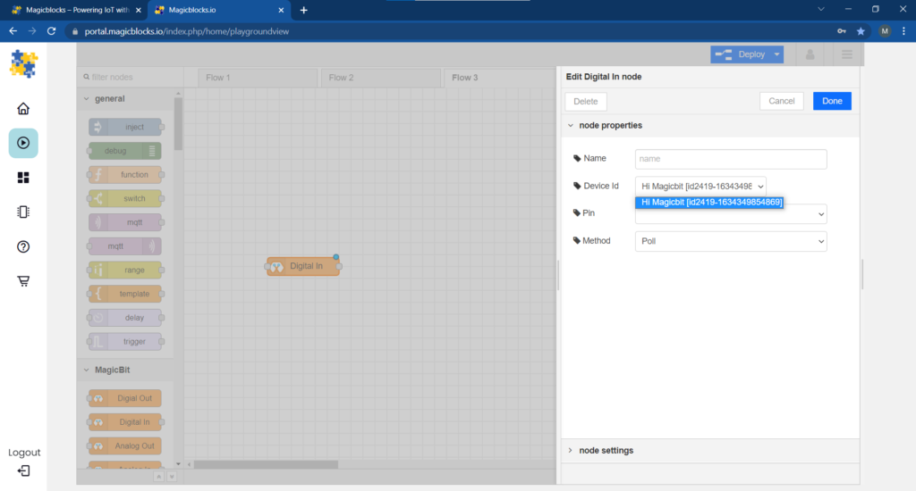
 2. Double-click on the Digital In block and select your unique Device ID from the drop-down menu.
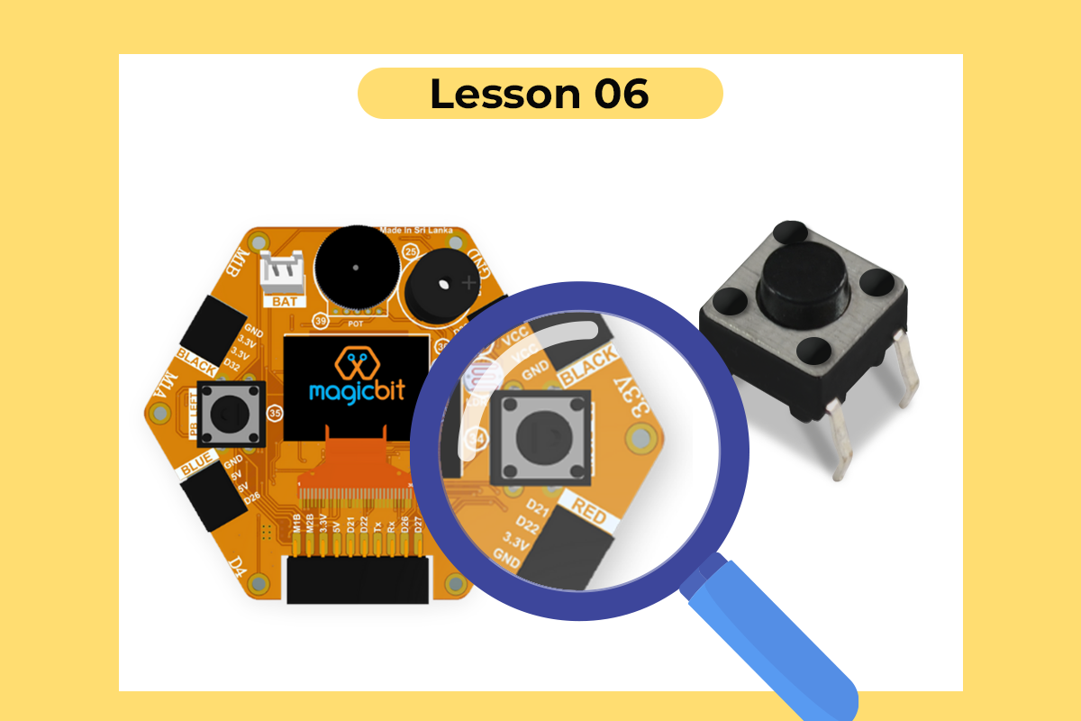
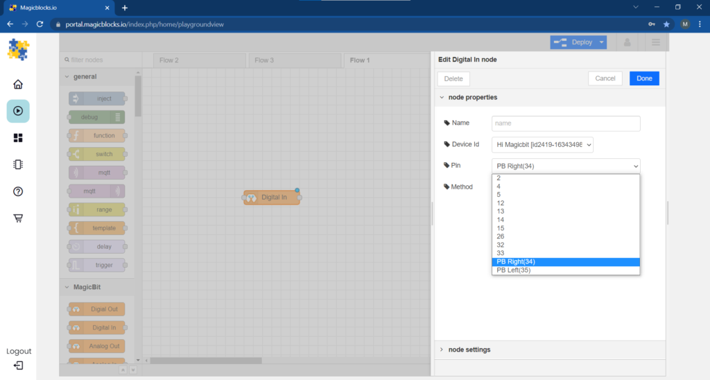
3. Choose ‘PB Right(34)’ or ‘PB Left(35)’ from the PIN drop-down menu.(Connects with the Right or Left Push input type Button on your Magicbit)
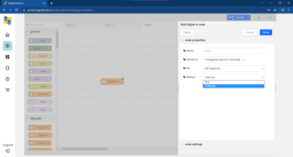
 4. Select the Method as Interrupt from the drop-down menu.
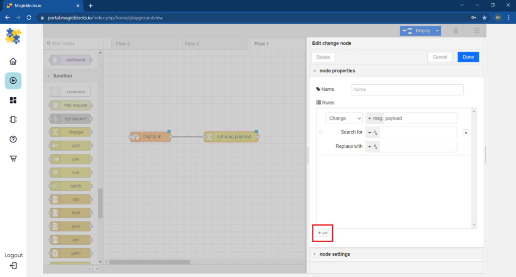
 Set up the Change Block
(This Node is used to change the 1 & 0 signal input from the Digital In node to any text you want)
1. Drag & Drop the Change Block from the function nodes section on the left of the screen to the flow.
 2. Add a new rule from the ‘+’ Button to use 2 rules.
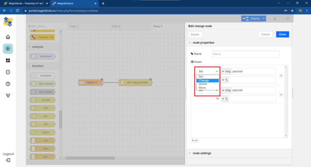
 3. Change the function of both of the rules from Set to Change from the drop-down menu.
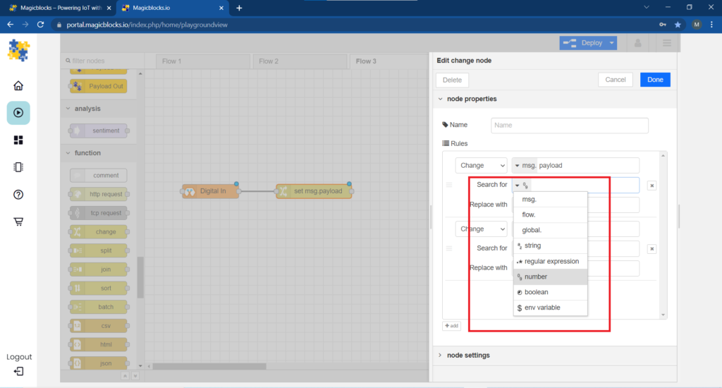
 4. Next, change the ‘Search for’ function from String(text) to Number in both of the rules. And make sure the ‘Replace with’ function is set to String(text).
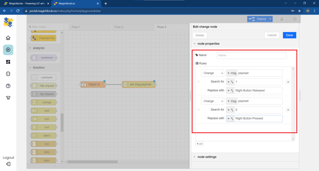
 5. Set up the rules.
- The First Rule is to search for ‘1’ in signal input and replace it with our text (E.g., ‘Right Button Released’ or ‘Right OFF’)
- The Second Rule, is to search for ‘0’ in signal input and replace it with our text (E.g., ‘Right Button Pressed’ or ‘Right ON’)
The text ‘Right’ or ‘Left’ depends on the Push Button which is linked to the Digital In Node in the above step.
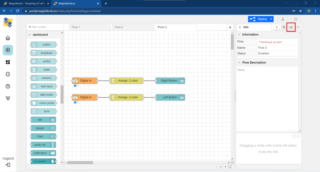
(image below shows an example of the rules)
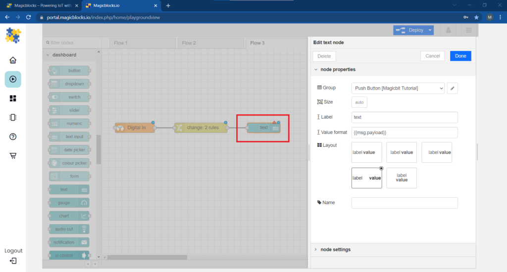
 Set up the Text Block
1. Drag & drop the Text block from the dashboard nodes section to the Flow.
2. Double-click on the text node and set up a basic dashboard UI [user- interface] from the drop-down menu and a name for your field.
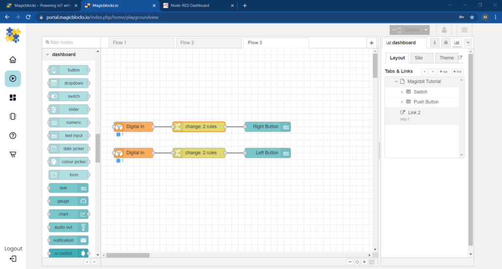
[Optional] Setup the same node configuration for the other Push input type Button
1. Copy & Paste the 3 nodes.
2. Change the PIN on the Digital In node for the other Push Button.
3. Change the Text in Change node from ‘Right’ to ‘Left’ or vice versa.
[Optional] Import Already Setup Nodes
If you had trouble setting up nodes, you can use the import feature in Magicblocks to get the nodes which have been already set up.
- First copy this code to your clipboard;
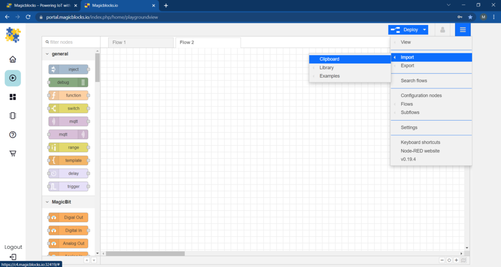
[{"id":"7e4ce5e8.78f72c","type":"change","z":"d2db2033.c2624","name":"","rules":[{"t":"change","p":"payload","pt":"msg","from":"1","fromt":"num","to":"Right Button Released","tot":"str"},{"t":"change","p":"payload","pt":"msg","from":"0","fromt":"num","to":"Right Button Pressed","tot":"str"}],"action":"","property":"","from":"","to":"","reg":false,"x":420,"y":1040,"wires":[["94824e1d.fc753"]]},{"id":"e4069d22.87f17","type":"DI","z":"d2db2033.c2624","name":"Right PB","epId":"","pin":"34","method":"1","x":240,"y":1040,"wires":[["7e4ce5e8.78f72c"]]},{"id":"94824e1d.fc753","type":"ui_text","z":"d2db2033.c2624","group":"b6e2a4f1.2e9cd8","order":0,"width":0,"height":0,"name":"","label":"Right Push Button","format":"{{msg.payload}}","layout":"row-spread","x":650,"y":1040,"wires":[]},{"id":"71d893be.8c5acc","type":"change","z":"d2db2033.c2624","name":"","rules":[{"t":"change","p":"payload","pt":"msg","from":"1","fromt":"num","to":"Left Button Released","tot":"str"},{"t":"change","p":"payload","pt":"msg","from":"0","fromt":"num","to":"Left Button Pressed","tot":"str"}],"action":"","property":"","from":"","to":"","reg":false,"x":420,"y":1100,"wires":[["37eaa40b.169e9c"]]},{"id":"43156a65.24a1f4","type":"DI","z":"d2db2033.c2624","name":"Left PB","epId":"","pin":"35","method":"1","x":240,"y":1100,"wires":[["71d893be.8c5acc"]]},{"id":"37eaa40b.169e9c","type":"ui_text","z":"d2db2033.c2624","group":"b6e2a4f1.2e9cd8","order":0,"width":0,"height":0,"name":"","label":"Left Push Button","format":"{{msg.payload}}","layout":"row-spread","x":640,"y":1100,"wires":[]},{"id":"b6e2a4f1.2e9cd8","type":"ui_group","z":"","name":"Proximity Sensor Module","tab":"1e4dddd7.63fc02","disp":true,"width":"10","collapse":false},{"id":"1e4dddd7.63fc02","type":"ui_tab","z":"","name":"Magicbit Tutorial","icon":"dashboard","order":1}]- Click on the options menu on the top right-hand corner of the screen.
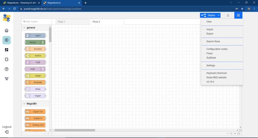
- Next, hover your cursor over the Import sub-menu.
 Then click on Clipboard and paste the code on your clipboard to the text field
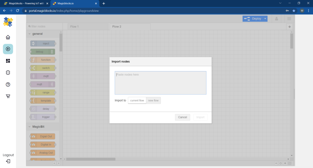
- Select current flow or new flow and click on Import.
IMPORTANT
Make sure you type your device ID on both of the Digital In node properties.
Finally, Deploying the Blocks
- Make sure all the blocks are connected.
- Click on the Deploy button on the top right-hand corner of the screen.
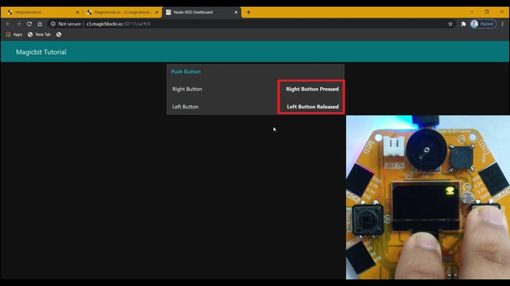
- After deploying, go to the dashboard UI by clicking the link to dashboard URL on the top right-hand corner of the screen.
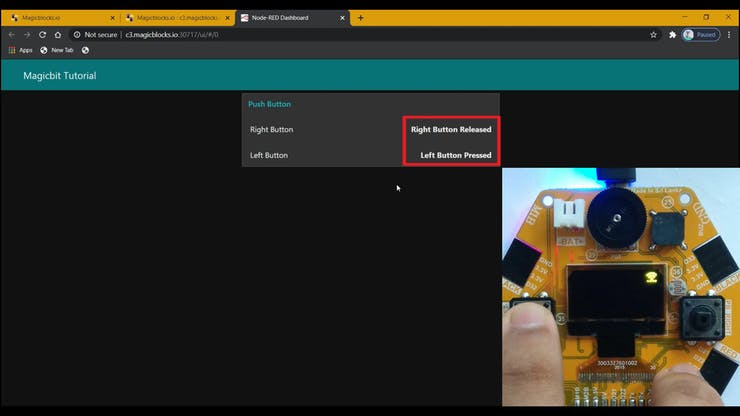
 Press the Left or Right Push Buttons and the text will be displayed on the Dashboard.
Troubleshooting
- Check whether your Magicbit is connected to the internet.
- Check whether the correct PINs are used (e.g., ‘PB Right(34)’ or ‘PB Left(35)’).
If you need help or couldn’t understand a step be sure to check out our YouTube video by clicking here: Youtube Video