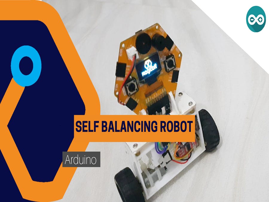
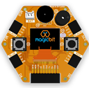
Self balancing robot from Magicbit
Make a self balancing robot using Magicbit dev. board
Components Required

Story
Hey guys, today in this tutorial we will learn about a few complex things. That is about a self-balancing robot using Magicbit with Arduino IDE. So let us get started.
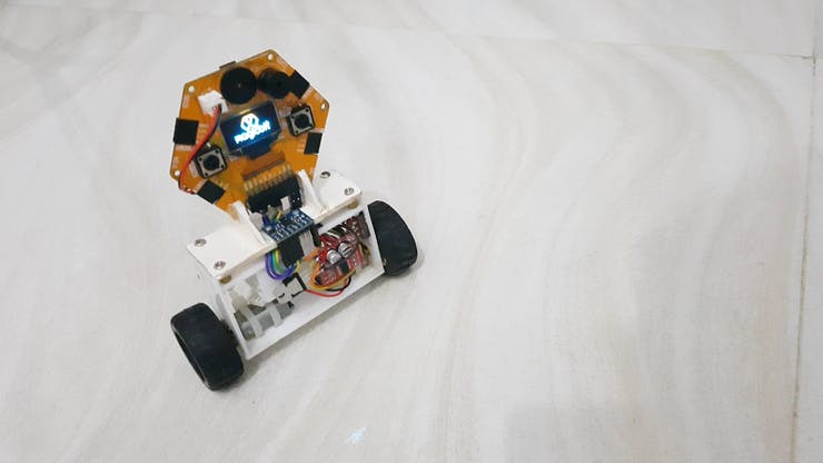
First of all, let’s look at what is a self-balancing robot. The self-balancing robot is a two-wheeled robot. The special feature is that the robot can be balancing itself without using any external support. When the power is on the robot will stand up and then balanced continuously by using oscillation movements. So now all of you have some rough idea about a self-balancing robot.
Theory and Methodology
To balance the robot, first, we get data from some sensors to measure the robot angle to the vertical plane. For that purpose, we used MPU6050. After getting the data from the sensor we calculate the tilt to the vertical plane. If the robot has a straight and balanced position, then the tilt angle is zero. If not, then the tilt angle is a positive or negative value. If the robot is tilted to the front side, then the robot should move in the front direction. Also if the robot is tilt to the reverse side then the robot should move to the reverse direction. If this tilt angle is high then the response speed should be high. Vice versa the tilt angle is low then the reaction speed is should below. To control this process we used a specific theorem called PID. PID is a control system used to control many processes. PID stands for 3 processes.
- P- proportional
- I- integral
- D- derivative
Every system has input and output. In the same way, this control system also has some input. In this control system that is the deviation from the stable state. We called that an error. In our robot, the error is the tilt angle from the vertical plane. If the robot is balanced then the tilt angle is zero. So the error value will be zero. Therefore the output of the PID system is zero. This system includes three separate mathematical processes.
- The first one is multiply error from numeric gain. This gain is usually called Kp.
P=error*Kp
- The second one is to generate the integral of the error in the time domain and multiply it from some of the gains. This gain called Ki
I= Integral(error)*Ki
- The third one is derivative of the error in the time domain and multiply it by some amount of gain. This gain is called Kd
D=(d(error)/dt)*kd
After adding the above operations we get our final output
OUTPUT=P+I+D
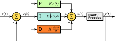
Because the P part robot can get a stable position that is proportional to the deviation. I part calculate the area of error vs time graph. So it tries to get the robot to a stable position always accurately. D part measures the slope in the time vs error graph. If the error is increasing this value is positive. If the error is decreasing this value is negative. Because of that, when the robot is moved to a stable position then the reaction speed will be decreased and this will help to remove unnecessary overshoots. You can learn more about PID theory from the link shown below.
The output of the PID function is limit to the 0-255 range(8 bit PWM resolution) and that will feed to motors as a PWM signal.
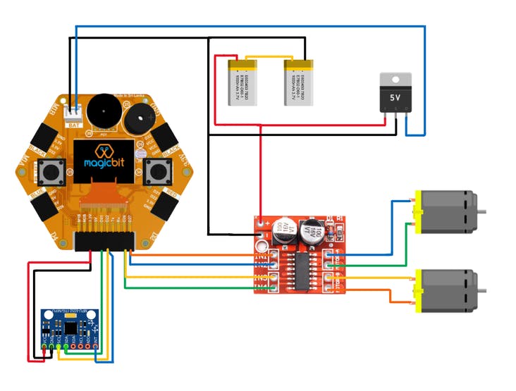
Hardware setup
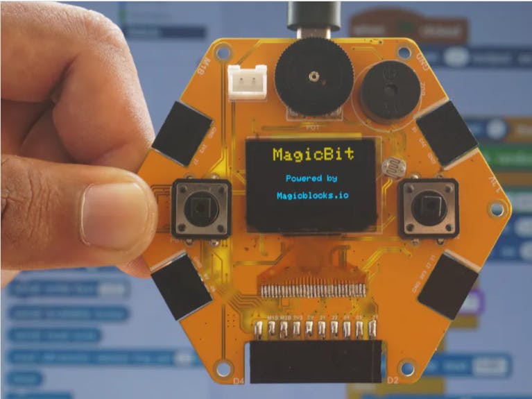
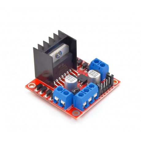
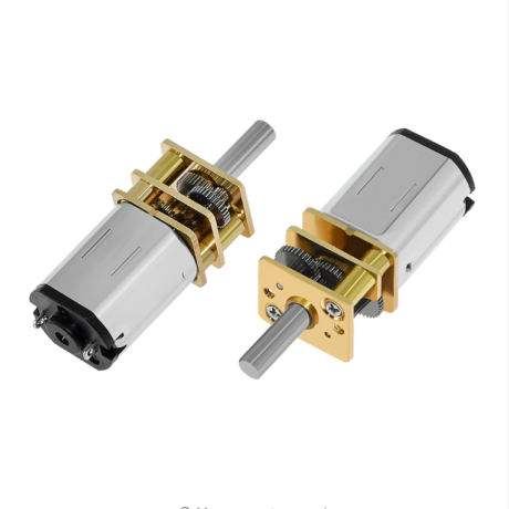
Now, this is the hardware setup part. The design of the robot depends on you. When you designed a robot’s body you have to consider symmetric it about a vertical axis which lies in the motor axis. The battery pack is located below. Therefore the robot is easy to balance. In our design, we fix the Magicbit board vertically to the body. We used two 12V gear motors. But you can use any kind of gear motor. that depends on your robot dimensions.
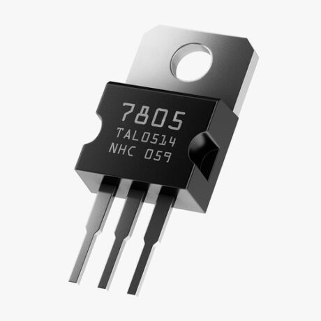
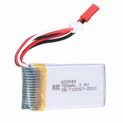
When we discuss the circuit it’s powered by a 7.4V Lipo battery. Magicbit used 5V for power. Therefore we used 7805 regulators to regulate battery voltage to 5V. In later versions of Magicbit that regulator is not needed. Because it powering up to 12V. We directly supply 7.4V for the motor drivers.
Connect all components according to the below diagram.
Software setup
In the code, we used the PID library to calculate PID output.
Go to the following link to download it.
https://www.arduinolibraries.info/libraries/pid
Download the latest version of it.
To get better sensor readings we used the DMP library. DMP stands for digital motion process. This is an inbuilt feature of MPU6050. This chip has an integrated motion process unit. So it takes reading and analysis. After it generates noiseless accurate outputs to the microcontroller (in this case Magicbit(ESP32)). But there are a lot of works on the microcontroller side to take those readings and calculate the angle. So to simply do that we used the MPU6050 DMP library. Download it by going to the following link.
https://github.com/ElectronicCats/mpu6050
To install the libraries, in the Arduino menu go-to tools-> include library->add.zip library and select the library file which you downloaded.
In the code, you have to change the setpoint angle correctly. The PID constant values are different from robot to robot. So in tuning that, first set Ki and Kd values zero and then increase Kp until you get better reaction speed. More Kp causes more overshoots. Then increase the Kd value. Increase it by always in very little amount. This value is generally low than other values. Now increase the Ki until you have very good stability.
Select the correct COM port and board type the. upload the code. Now you can play with your DIY robot.
Code
#include <PID_v1.h>
#include "I2Cdev.h"
#include "MPU6050_6Axis_MotionApps20.h"

#if I2CDEV_IMPLEMENTATION == I2CDEV_ARDUINO_WIRE
    #include "Wire.h"
#endif


MPU6050 mpu;


bool dmpReady = false;  // set true if DMP init was successful
uint8_t mpuIntStatus;   // holds actual interrupt status byte from MPU
uint8_t devStatus;      // return status after each device operation (0 = success, !0 = error)
uint16_t packetSize;    // expected DMP packet size (default is 42 bytes)
uint16_t fifoCount;     // count of all bytes currently in FIFO
uint8_t fifoBuffer[64]; // FIFO storage buffer

Quaternion q;           // [w, x, y, z]         quaternion container
VectorFloat gravity;    // [x, y, z]            gravity vector
float ypr[3];           // [yaw, pitch, roll]   yaw/pitch/roll container and gravity vector


double originalSetpoint = 172.5;
double setpoint = originalSetpoint;
double movingAngleOffset = 0.1;
double input, output;
int moveState=0;
double Kp = 23;//set P first
double Kd = 0.8;//this value generally small
double Ki = 300;//this value should be high for better stability
PID pid(&input, &output, &setpoint, Kp, Ki, Kd, DIRECT);//pid initialize

int motL1=26;//4 pins for motor drive
int motL2=2;
int motR1=27;
int motR2=4;


volatile bool mpuInterrupt = false;     // indicates whether MPU interrupt pin has gone high
void dmpDataReady()
{
    mpuInterrupt = true;
}


void setup()
{
  ledcSetup(0, 20000, 8);//pwm setup
  ledcSetup(1, 20000, 8);
  ledcSetup(2, 20000, 8);
  ledcSetup(3, 20000, 8);
  ledcAttachPin(motL1, 0);//pinmode of motors
  ledcAttachPin(motL2, 1);
  ledcAttachPin(motR1, 2);
  ledcAttachPin(motR2, 3);
    // join I2C bus (I2Cdev library doesn't do this automatically)
  #if I2CDEV_IMPLEMENTATION == I2CDEV_ARDUINO_WIRE
  Wire.begin();
  Wire.setClock(400000); // 400kHz I2C clock. Comment this line if having compilation difficulties
#elif I2CDEV_IMPLEMENTATION == I2CDEV_BUILTIN_FASTWIRE
  Fastwire::setup(400, true);
#endif
  Serial.println(F("Initializing I2C devices..."));

  pinMode(14, INPUT);
    // initialize serial communication
    // (115200 chosen because it is required for Teapot Demo output, but it's
    // really up to you depending on your project)
    Serial.begin(9600);
    while (!Serial); // wait for Leonardo enumeration, others continue immediately

    // initialize device
    Serial.println(F("Initializing I2C devices..."));
    mpu.initialize();

    // verify connection
    Serial.println(F("Testing device connections..."));
    Serial.println(mpu.testConnection() ? F("MPU6050 connection successful") : F("MPU6050 connection failed"));

    // load and configure the DMP
    Serial.println(F("Initializing DMP..."));
    devStatus = mpu.dmpInitialize();

    // supply your own gyro offsets here, scaled for min sensitivity
    mpu.setXGyroOffset(220);
    mpu.setYGyroOffset(76);
    mpu.setZGyroOffset(-85);
    mpu.setZAccelOffset(1788); // 1688 factory default for my test chip

    // make sure it worked (returns 0 if so)
    if (devStatus == 0)
    {
        // turn on the DMP, now that it's ready
        Serial.println(F("Enabling DMP..."));
        mpu.setDMPEnabled(true);

        // enable Arduino interrupt detection
        Serial.println(F("Enabling interrupt detection (Arduino external interrupt 0)..."));
        attachInterrupt(14, dmpDataReady, RISING);
        mpuIntStatus = mpu.getIntStatus();

        // set our DMP Ready flag so the main loop() function knows it's okay to use it
        Serial.println(F("DMP ready! Waiting for first interrupt..."));
        dmpReady = true;

        // get expected DMP packet size for later comparison
        packetSize = mpu.dmpGetFIFOPacketSize();

        //setup PID

        pid.SetMode(AUTOMATIC);
        pid.SetSampleTime(10);
        pid.SetOutputLimits(-255, 255);
    }
    else
    {
        // ERROR!
        // 1 = initial memory load failed
        // 2 = DMP configuration updates failed
        // (if it's going to break, usually the code will be 1)
        Serial.print(F("DMP Initialization failed (code "));
        Serial.print(devStatus);
        Serial.println(F(")"));
    }
}


void loop()
{
    // if programming failed, don't try to do anything
    if (!dmpReady) return;

    // wait for MPU interrupt or extra packet(s) available
    while (!mpuInterrupt && fifoCount < packetSize)
   {

        pid.Compute();//this time period is used to load data,so you can use this for other calculations
        motorSpeed(output);

    }

    // reset interrupt flag and get INT_STATUS byte
    mpuInterrupt = false;
    mpuIntStatus = mpu.getIntStatus();

    // get current FIFO count
    fifoCount = mpu.getFIFOCount();

    // check for overflow (this should never happen unless our code is too inefficient)
    if ((mpuIntStatus & 0x10) || fifoCount == 1024)
    {
        // reset so we can continue cleanly
        mpu.resetFIFO();
        Serial.println(F("FIFO overflow!"));

    // otherwise, check for DMP data ready interrupt (this should happen frequently)
    }
    else if (mpuIntStatus & 0x02)
    {
        // wait for correct available data length, should be a VERY short wait
        while (fifoCount < packetSize) fifoCount = mpu.getFIFOCount();

        // read a packet from FIFO
        mpu.getFIFOBytes(fifoBuffer, packetSize);

        // track FIFO count here in case there is > 1 packet available
        // (this lets us immediately read more without waiting for an interrupt)
        fifoCount -= packetSize;

        mpu.dmpGetQuaternion(&q, fifoBuffer);
        mpu.dmpGetGravity(&gravity, &q);
        mpu.dmpGetYawPitchRoll(ypr, &q, &gravity);
        #if LOG_INPUT
            Serial.print("ypr\t");
            Serial.print(ypr[0] * 180/M_PI);//euler angles
            Serial.print("\t");
            Serial.print(ypr[1] * 180/M_PI);
            Serial.print("\t");
            Serial.println(ypr[2] * 180/M_PI);
        #endif
        input = ypr[1] * 180/M_PI + 180;
   }
}
void motorSpeed(int PWM){

float L1,L2,R1,R2;

if(PWM>=0){//forward direction

  L2=0;
  L1=abs(PWM);
  R2=0;
  R1=abs(PWM);
  if(L1>=255){
    L1=R1=255;
  }
}
else {//backward direction
  L1=0;
   L2=abs(PWM);
   R1=0;
  R2=abs(PWM);
  if(L2>=255){
    L2=R2=255;
  }
}

//motor drive
ledcWrite(0,  L1);
ledcWrite(1,  L2);
ledcWrite(2,  R1*0.97);//0.97 is speed factor,because right motor have high speed than left motor,so we reduce it until motor speeds are equal
ledcWrite(3,  R2*0.97);
}
If you need help or couldn’t understand a step be sure to check out our YouTube video by clicking here: Youtube Video