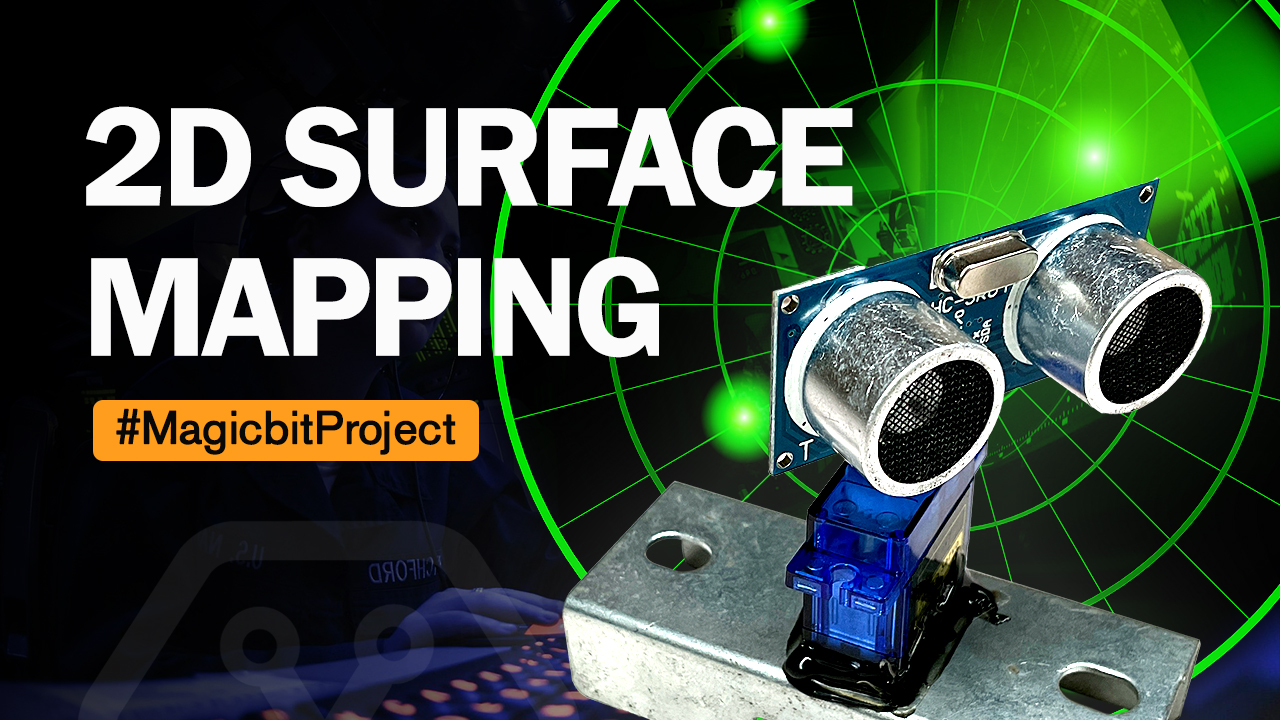
2D surface Mapping
Components Required
Introduction
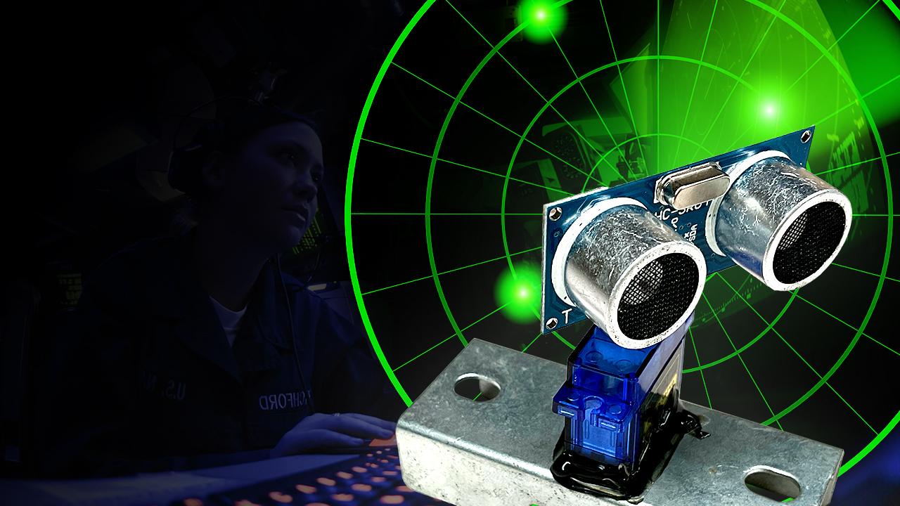
In this project, we will make a 2D surface mapper. This is very much like a radar. We will be using Processing software to read the data from the serial monitor
Processing? Download here
Processing is a graphics library that is compatible with Arduino. we will be using it to draw the 2D map(radar) and plot/show our data on it. You can download it from here. https://processing.org/
What You Need
- A Magic bit board
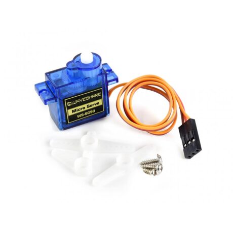
- A servo
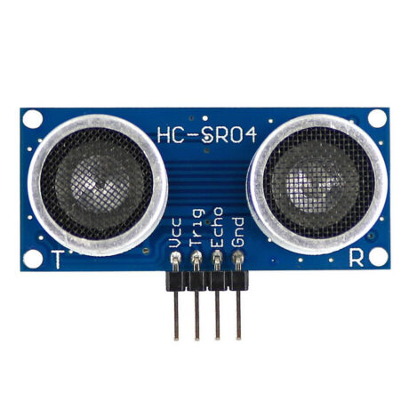
- An untrasonic sensor
- Wires
Method
First, you must mount the ultrasonic sensor on the servo. Then connect both of them to the board. We will wire both Echo and trigger pins together.
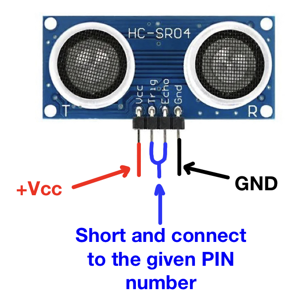
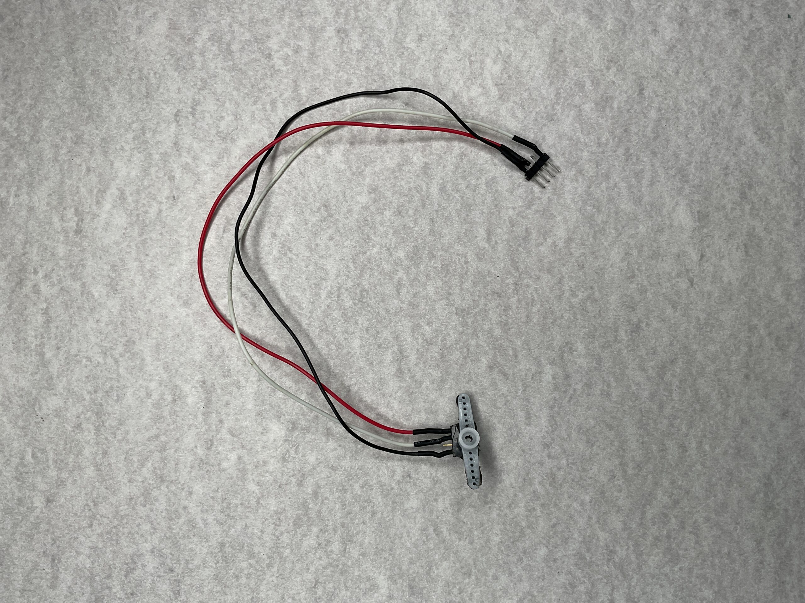
You can use a homemade connector like the one below to connect the ultrasonic sensor to the magic nit board. Use headers and pins.
Then you can use this connector to connect the servo and the ultrasonic sensor. mount the servo on a bracket steadily.
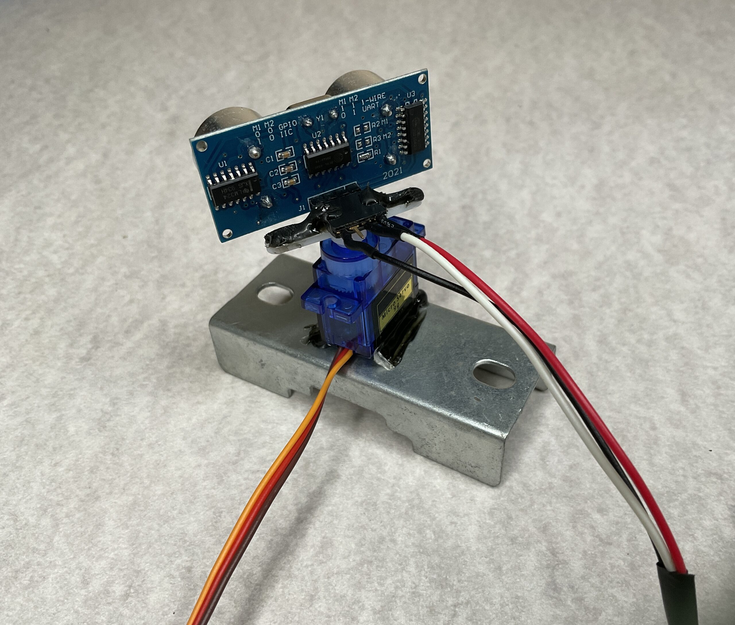
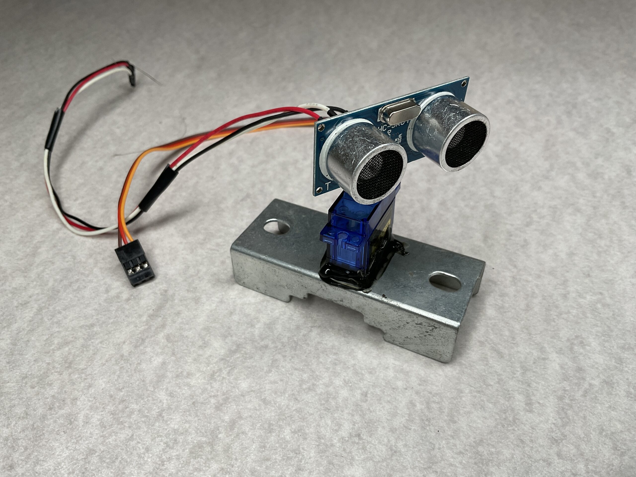
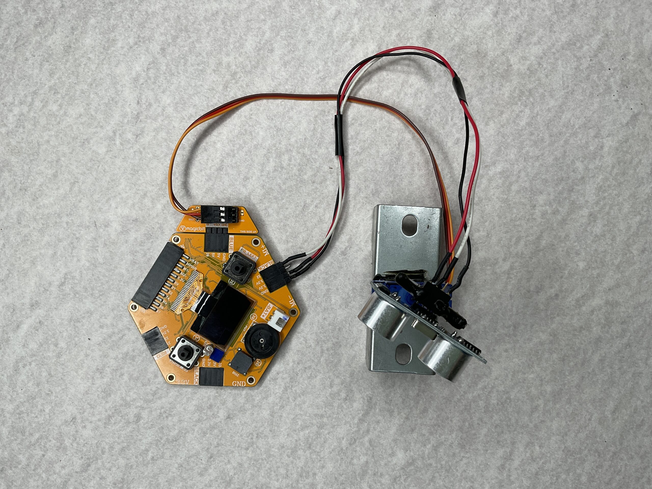
Use pin 32 for the Ultrasonic sensor and pin 26 for the servo. When you connect everything properly, it will look like this.
Upload the below code to the Magicbit board using Arduino.
#include <ESP32Servo.h>
#include <NewPing.h>
#define TRIGGER_PIN  32
#define ECHO_PIN     32
#define MAX_DISTANCE 200

int distance;

NewPing sonar(TRIGGER_PIN, ECHO_PIN, MAX_DISTANCE);
Servo s1;

void setup() {

  Serial.begin(115200);

  s1.attach(26);
}

void loop()
{
    for(int i=15;i<=165;i++){            // rotates the servo motor from 15 to 165 degrees
    s1.write(i);
    delay(30);
    distance = sonar.ping_cm();

    Serial.print(i);                      // Sends the current degree into the Serial Port
    Serial.print(",");                   // Sends addition character right next to the previous value needed later in the Processing IDE for indexing
    Serial.print(distance);                // Sends the distance value into the Serial Port
    Serial.print(".");                   // Sends addition character right next to the previous value needed later in the Processing IDE for indexing
      }

    for(int i=165;i>15;i--){
    s1.write(i);
    delay(30);
    distance = sonar.ping_cm();
    Serial.print(i);
    Serial.print(",");
    Serial.print(distance);
    Serial.print(".");
    }

}
After that, run the following code on the processing software. This is used to output the data graphically. Be sure to read from the same serial monitor as used in Arduino. (Change the line 11)
import processing.serial.*;               // imports library for serial communication

Serial myPort;                         // defines Object for Serial
String ang="";
String distance="";
String data="";
int angle, dist;

void setup() {
   size (1200, 700);
   myPort = new Serial(this,"/dev/cu.usbserial-1410", 115200);   // starts the serial communication. Changfe this to suit your serial monitor on Arduino
   myPort.bufferUntil('.');    // reads the data from the serial port up to the character '.' before calling serialEvent
   background(0);
}

void draw() {
      drawText();
      drawRadar();
      drawObject();
      if(angle==165 || angle == 15){
      background(0,0,0);
      }

      fill(0,5);
      noStroke();
      noStroke();
      fill(0,255);
      rect(0,height*0.93,width,height);                   // so that the text having angle and distance doesnt blur out
}

void serialEvent (Serial myPort) {                                                     // starts reading data from the Serial Port
                                                                                      // reads the data from the Serial Port up to the character '.' and puts it into the String variable "data".
      data = myPort.readStringUntil('.');
      data = data.substring(0,data.length()-1);

      int index1 = data.indexOf(",");
      ang= data.substring(0, index1);
      distance= data.substring(index1+1, data.length());

      angle = int(ang);
      dist = int(distance);
      System.out.println(angle);
}

void drawRadar()
{
    pushMatrix();
    noFill();
    stroke(10,255,10);        //green
    strokeWeight(1);
    translate(width/2,height-height*0.06);
    line(-width/2,0,width/2,0);
    arc(0,0,(width*0.5),(width*0.5),PI,TWO_PI);
    arc(0,0,(width*0.25),(width*0.25),PI,TWO_PI);
    arc(0,0,(width*0.75),(width*0.75),PI,TWO_PI);
    arc(0,0,(width*0.95),(width*0.95),PI,TWO_PI);
    line(0,0,(-width/2)*cos(radians(90)),(-width/2)*sin(radians(90)));
    popMatrix();
}
void drawObject() {
    strokeWeight(7);
    stroke(255,0,0);
    translate(width/2,height-height*0.06);
    float pixleDist = (dist/40.0)*(width/2.0);                        // covers the distance from the sensor from cm to pixels
    float x=-pixleDist*cos(radians(angle));
    float y=-pixleDist*sin(radians(angle));
    if(dist<=40)                                                  // limiting the range to 40 cms
    {
       point(-x,y);
    }
}

void drawText()
{
    pushMatrix();
    fill(100,200,255);
    textSize(25);
    text("10cm",(width/2)+(width*0.115),height*0.93);
    text("20cm",(width/2)+(width*0.24),height*0.93);
    text("30cm",(width/2)+(width*0.365),height*0.93);
    text("40cm",(width/2)+(width*0.45),height*0.93);
   translate(width/2,height-height*0.06);
   textSize(25);
   text(" 30°",(width/2)*cos(radians(30)),(-width/2)*sin(radians(30)));
   text(" 60°",(width/2)*cos(radians(60)),(-width/2)*sin(radians(60)));
   text("90°",(width/2)*cos(radians(91)),(-width/2)*sin(radians(90)));
   text("120°",(width/2)*cos(radians(123)),(-width/2)*sin(radians(118)));
   text("150°",(width/2)*cos(radians(160)),(-width/2)*sin(radians(150)));
   popMatrix();
}
After uploading the processing code, run it. You will see in the graphical interface, servo and ultrasonic sensor scanning the 2D area.