
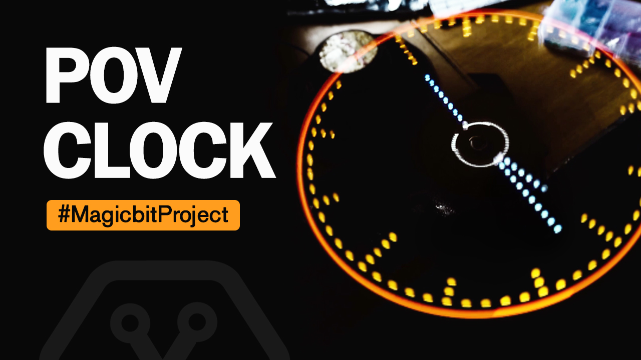
Analog style POV Clock
Components Required


Introduction
In this project, we will make a analog-styled POV clock. This is a fun project that you can do very easily at home. The way you connect the wires and place the components could be different from the method we have shown below and it is totally fine! You will be okay if you follow the circuit diagram and follow the instructions properly.
What is POV (Persistance of vision)?
Persistence of vision traditionally refers to the optical illusion that occurs when visual perception of an object does not cease for some time after the rays of light proceeding from it have ceased to enter the eye
Instructions
Make sure you have the following items.
- A Magicbit board.
- 17 LEDs of preferred color(Check the circuit diagram).
- 17 Hundred Ohm resistors.
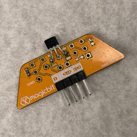
- A hall effect sensor
- A strong magnet
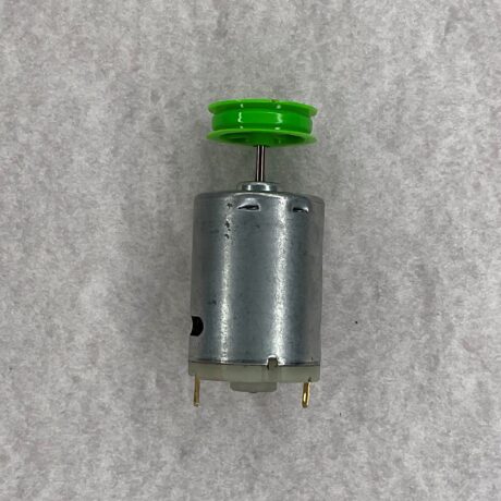
- 12 V motor and a separate source to power it
- A battery to power the circuit.
- Wires
- A Vero board
- A hot glue gun and maybe some zip ties to securely connect the components
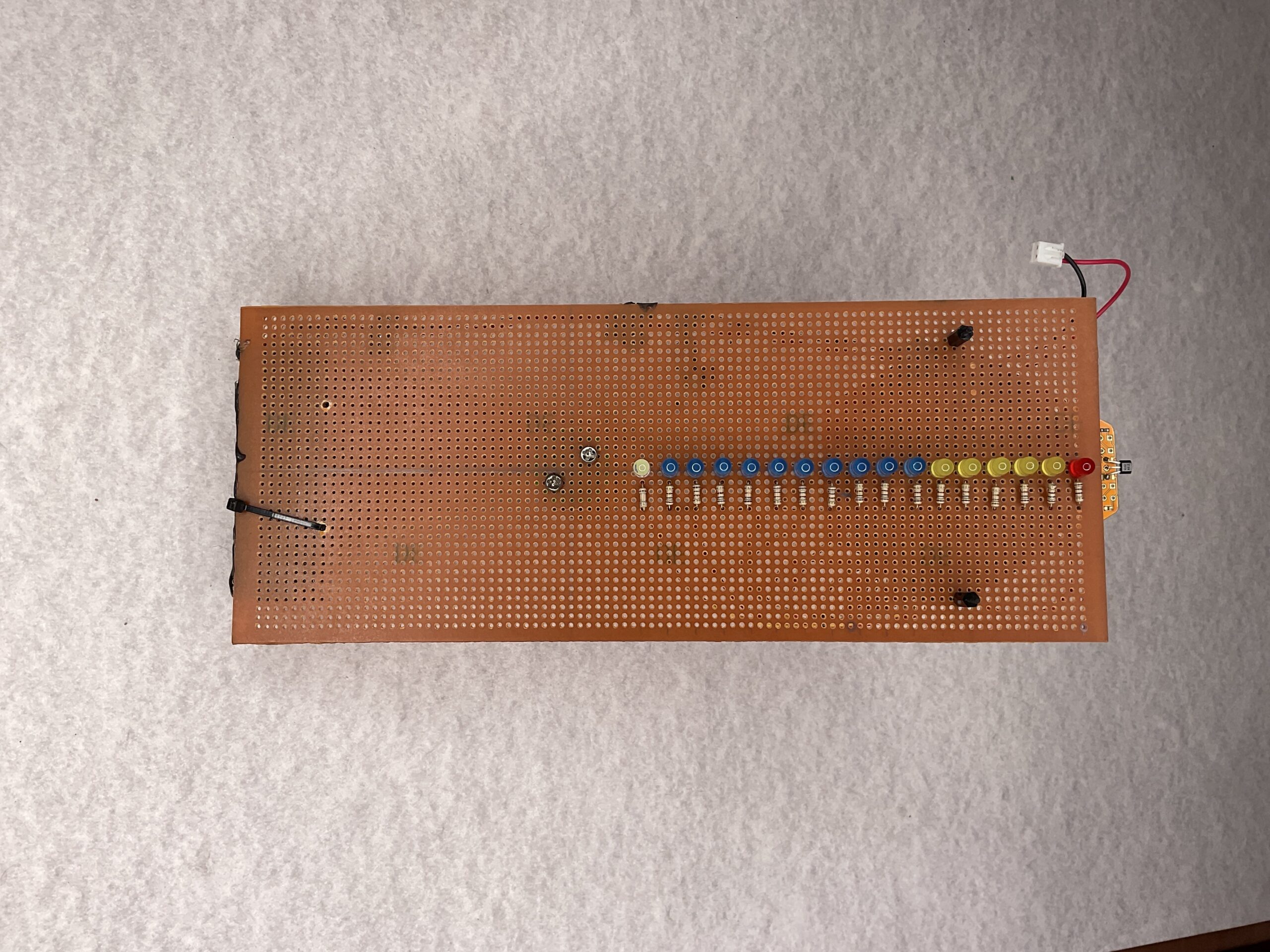
First, you have to assemble the given circuit. Follow the circuit diagram and make the connections.
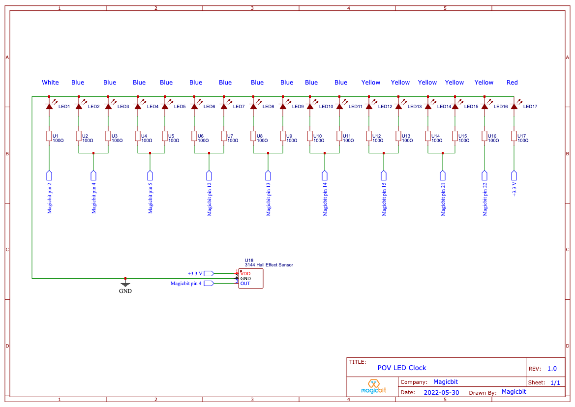
Use a Vero board or a suitable low-weight board. Solder LEDs in a line according to the pattern and wire them to a Magicbit through resistors.
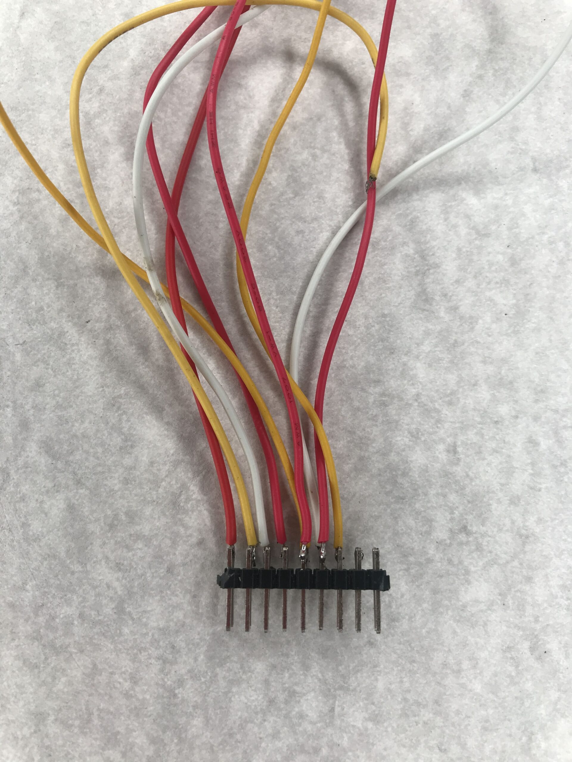
You can make your own connector as shown below to connect all the wires to the Magicbit board
You will need to fix the Hall Effect sensor which you can access easily (far away from the motor axis so you have enough room to place a magnet near it when rotating).
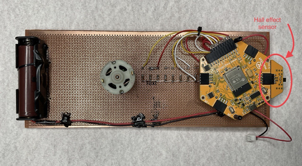
Next, mount the board to a 12v DC motor. Make sure that the center of gravity of the circuit is at the axis of rotation. this will ensure a smooth rotation. Using a coupling will be easier. You can mount the motor to a desk or a stand
Now, upload the given code.
// POV LED Clock
// Magicbit
//

int LED1 = 2;
int LED2_3 = 4;
int LED4_5 = 5;
int LED6_7 = 12;
int LED8_9 = 13;
int LED10_11 = 14;
int LED12_13 = 15;
int LED14_15 = 21;
int LED16 = 22;

int sensorPin = 33;

unsigned int n,ADCvalue,propeller_posn;
unsigned long previousTime = 0;

byte hours = 12;    // set hours
byte minutes = 15;  // set minutes
byte seconds = 00;  // set seconds

int val;

void setup()
{
  pinMode(LED1,OUTPUT);
  pinMode(LED2_3,OUTPUT);
  pinMode(LED4_5,OUTPUT);
  pinMode(LED6_7,OUTPUT);
  pinMode(LED8_9,OUTPUT);
  pinMode(LED10_11,OUTPUT);
  pinMode(LED12_13,OUTPUT);
  pinMode(LED14_15,OUTPUT);
  pinMode(LED16,OUTPUT);

  pinMode(sensorPin,INPUT_PULLUP);

  if(hours == 12)
  hours = 0;
}

void loop()
{
    val = digitalRead(sensorPin);

    while (val == LOW)
  {
    val = digitalRead(sensorPin);
  }


  if (millis() >= (previousTime))
  {
     previousTime = previousTime + 1000;
     seconds = seconds+1;
     if (seconds == 60)
     {
        seconds = 0;
        minutes = minutes+1;
     }
     if (minutes == 60)
     {
        minutes = 0;
        hours = hours+1;
     }
     if (hours == 12)
     {
        hours = 0;
     }
  }

  propeller_posn=30;
  n=0;

  while(n < 60)
  {

  drawMinuteMarker();

  if ((propeller_posn==0) || (propeller_posn==5) || (propeller_posn==10) || (propeller_posn==15) || (propeller_posn==20) || (propeller_posn==25) || (propeller_posn==30) || (propeller_posn==35) || (propeller_posn==40) || (propeller_posn==45) || (propeller_posn==50) || (propeller_posn==55))
  drawHourMarker();

  if ((propeller_posn==0) || (propeller_posn==15) || (propeller_posn==30) || (propeller_posn==45))
  drawQuarterMarker();

  if((propeller_posn == hours*5) || (( propeller_posn == 0 ) && (hours == 0)))
  drawHoursHand();

  if(propeller_posn == minutes)
  drawMinutesHand();

  if(propeller_posn == seconds)
  drawSecondsHand();

  delayMicroseconds(380);     // for LED pixel width   (change the value according to motor speed. Increase for low speed, decrease for high speed motor)

  displayClear();

  drawInner_Circle();

  delayMicroseconds(600);   // for the gap between LED pixels/minutes markers  (change the value according to motor speed. Increase for low speed, decrease for high speed motor)

  n++;
  propeller_posn++;
  if(propeller_posn == 60)
  propeller_posn=0;
  }

    val = digitalRead(sensorPin);

    while (val == HIGH)
    {
    val = digitalRead(sensorPin);
    }
}

//=========================

void displayClear()
  {
  digitalWrite(LED1,LOW);
  digitalWrite(LED2_3,LOW);
  digitalWrite(LED4_5,LOW);
  digitalWrite(LED6_7,LOW);
  digitalWrite(LED8_9,LOW);
  digitalWrite(LED10_11,LOW);
  digitalWrite(LED12_13,LOW);
  digitalWrite(LED14_15,LOW);
  digitalWrite(LED16,LOW);
  }

  void drawMinuteMarker()
  {
  digitalWrite(LED16,HIGH);
  }

  void drawHourMarker()
  {
  digitalWrite(LED14_15,HIGH);
  }

  void drawQuarterMarker()
  {
  digitalWrite(LED12_13,HIGH);
  }

  void drawHoursHand()
  {
  digitalWrite(LED1,HIGH);
  digitalWrite(LED2_3,HIGH);
  digitalWrite(LED4_5,HIGH);
  digitalWrite(LED6_7,HIGH);
  }

  void drawMinutesHand()
  {
  digitalWrite(LED1,HIGH);
  digitalWrite(LED2_3,HIGH);
  digitalWrite(LED4_5,HIGH);
  digitalWrite(LED6_7,HIGH);
  digitalWrite(LED8_9,HIGH);
  }

  void drawSecondsHand()
  {
  digitalWrite(LED1,HIGH);
  digitalWrite(LED2_3,HIGH);
  digitalWrite(LED4_5,HIGH);
  digitalWrite(LED6_7,HIGH);
  digitalWrite(LED8_9,HIGH);
  digitalWrite(LED10_11,HIGH);
  }

  void drawInner_Circle()
  {
  digitalWrite(LED1,HIGH);
  delayMicroseconds(30);
  digitalWrite(LED1,LOW);
  }
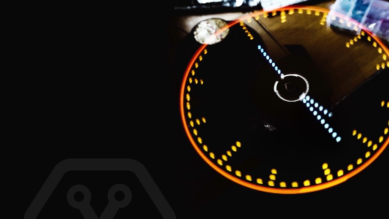
Power the motor and keep the magnet (use a strong magnet) where the Hall Effect sensor can sense it. If you do the steps correctly, you will see an analog clock.
Troubleshooting
- Sometimes you won’t see a full clock. This depends on the motor speed(RPM). To solve this, you need to change the values of “delayMicroseconds()” in the code.
- Maybe your clock is not showing although the motor is rotating. Check your connections to see if they are loose. Due to the centrifugal force acting on the components(battery for example), they can have loose connections.
- You should hear a flick sound every time the hall effect sensor crosses the magnetic field. If not, you won’t see the clock working. Make sure to use a strong magnet.
- download Arduino – https://www.arduino.cc/
Warning!
Be sure that everything is firmly attached to the board before you start rotating. Otherwise, they will fly around and cause damage. You can use zip ties and hot glue to make sure everything is fixed to the board.