
RGB Module
Use RGB LED to change colors as required
Components Required
Introduction
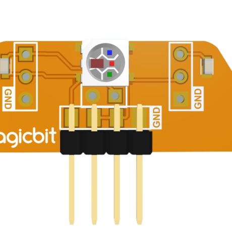
Magicbit RGB module consists of a WS2812B, also called a neopixel LED. You can cascade 100 s of these LEDs and control individually just using a single pin.
Learning outcomes:
- Learning to control a neopixel LED using micropython.
Theory
The RGB color model is an additive color model in which red, green, and blue light are added together in various ways to reproduce a broad array of colors. The name of the model comes from the initials of the three additive primary colors, red, green, and blue. The main purpose of the RGB color model is for the sensing, representation, and display of images in electronic systems, such as televisions and computers, though it has also been used in conventional photography. Before the electronic age, the RGB color model already had a solid theory behind it, based on human perception of colors. WS2812 has 3 LEDs built inside with a controller which can generate the color as you wish using only one microcontroller pin.
Methodology
Connect RGB module to port dedicated to pin 26 (bottom left corner). And run the following code from thonny IDE. After running the code, you can press the buttons on magicbit to change the color.
Code
from machine import Pin
from neopixel import NeoPixel
from random import randint

pin = Pin(26, Pin.OUT)
np = NeoPixel(pin, 1)

np[0] = (100,0,0)
np.write()

button_a=Pin(34, Pin.IN)
button_b=Pin(35, Pin.IN)
redVal = randint(0, 255)
greenVal = 0
blueVal = 0

while True:
    if button_a.value():
        redVal = 0
        blueVal = 0
        greenVal = randint(0, 255)
        np[0] = (greenVal, redVal, blueVal)
        np.write();

    elif button_b.value():
        redVal = 0
        blueVal = randint(0, 255)
        greenVal = 0
        np[0] = (redVal, greenVal, blueVal)
        np.write();
    else:
        np[0] = (greenVal, redVal, blueVal)
        np.write();
Explanation
You should see your LED turn green. If you press the A button on the Magicbit, the color will change to green, and if you press the B button, the color will change to blue.