

Simple Radar System From Magicbit
Make a simple radar system using HC-SR04 sensor and Microbit dev board with processing and Arduino IDE's.
Components Required


Story
In this tutorial we will learn about how to make a simple radar system using Magicbit core dev board. For this purpose we use HC-SR04 ultrasonic sensor and to displaying data, we use processing environment. Lets get start.
Theory and Methodology
First, lets discuss how does this work. The principle is very easy. First we rotate our sensor around vertical axis in 180 degree range continuously. During that motion we take the data about distance to nearest object from ultrasonic sensor at every angle. For this process we use Magicbit core board. After, we have to establish the connection with processing environment for showing our data. Therefor we use serial communication protocol with suitable baud rate. Then we design our radar system interface by using processing IDE. In that IDE we configure our serial communication for get real time data via serial. So we do real time communication with Magicbit and show the the data which send from Magicbit to the processing IDE.
Hardware setup
For this project we mainly used three hardware components. They are Magicbit, servo motor and ultrasonic sensor. The connection between all these parts are shown in below Figure.
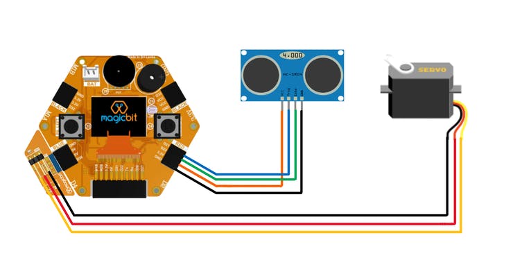
Ultrasonic sensor used 3.3 v for power up. Therefor we used right lower port of Magicbit board to connect ultrasonic sensor to Magicbit. But servo motor is used 5V for proper working, Therefor we used left lower port to connect servo motor with Magicbit. In this case, we use Magic bit servo connector module. But if you don’t have that module you can use three jumper wires to connect 5V to 5V, Gnd to Gnd and signal pin to 26 pin on magicbit.
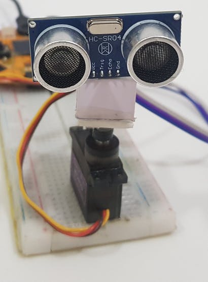
After build the circuit we have small mechanical part to build. set single side servo connector to servo motor using small nut. Then fix the sensor on that connector using some L shaped bracket or proper way. After the whole system we fixed on breadboard. But you can use other surface to mount servo and Magicbit.
Software Setup
The software side is littlebit complex. For proper understand you can refer the following links to before move on next part.
https://magicbit-arduino.readthedocs.io/en/latest/
https://hello.processing.org/editor/
Let’s look at Arduino IDE code and how that code is work.
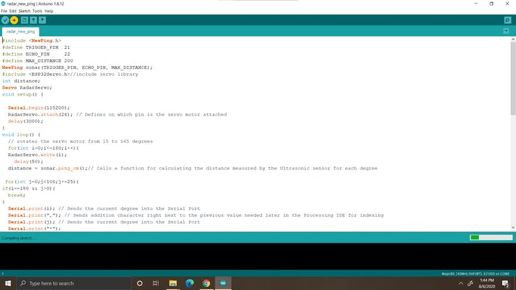
For driving servo we use ESP32 servo library. This library almost include in magic bit board manager in Arduino IDE. To deal with ultrasonic sensor we use newPing library. This can be download from following link.
https://bitbucket.org/teckel12/arduino-new-ping/downloads/
Download the zip file and and go tools>include library>add Zip library in Arduino. now select your downloaded zip file of new pin library. For communicate with processing we used serial communication with 115200 baud rate. This is most proper frequency for ESP32. At every angle we send our data to computer using this protocol. Distance to the nearest front object from the sensor, direction of rotation and rotate angle are include in this data. Using two for loops we rotate our servo in two direction. While one degree rotation we sent serial data at 4 times. The reason for that you can understand in processing part explanation.
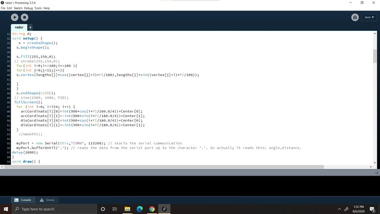
Now it’s time to look at processing environment. This is java based programming software. We can write sketch of our programme in this sketch in processing IDE. We can also generate visual output from running our programme. Also you can take output as 2D and 3d objects. Not only that, this can used for image processing and many more things.
In the processing sketch first we design our data display interface using simple graphic functions. At the start of the code we establish our serial communication by including serial libraries. In the setup function you have to do some change according which USB port you used to connect Magicbit with computer. you can check your port using Arduino IDE when you setup the Arduino IDE to uploading the code. Then change com port name in setup part in processing sketch. when the serial data is available, Serialevent function is automatically triggering. Therefor the main logic of the code is include in serial event for prevent the angles and data missing. when new data is available, we draw a line in the screen according to our angle.At that time if there is no object detect, then full line is green colored. If not then some portion of the line will be red according to distance from sensor to object. Also the according rotation direction we draw another 200 lines near to that line with decreasing level of green color. between each Main we have 0.25 degree difference. Therefor we get 4 readings at a time from Magicbit in each degree rotation. Because of that we can create beautiful searching hand in screen.
After uploading code success fully to magic and set hardware part successfully open the processing IDE and run the code by clicking run button. Now you have very simple radar system.
You can customize the codes as you wish what you want to display.
Troubleshooting
Processing sketch is not running,
- Wait some time. Because of the start up time is depend on your PC and GPU performance.
- Check the serial port number is correct on processing sketch.
- Check the USB connection is fixed correctly.
- Check the connection between ultrasonic sensor and Magicbit.
- Open the serial monitor and check the data is coming from Arduino. If not, then problem is your Arduino code or on your USB connection.
Servo is not working,
- Check the USB connection is fixed correctly.
- Check the wiring.
- Check the servo is in good condition.
Code
#include <NewPing.h>
#define TRIGGER_PIN  21
#define ECHO_PIN     22
#define MAX_DISTANCE 200
NewPing sonar(TRIGGER_PIN, ECHO_PIN, MAX_DISTANCE);
#include <ESP32Servo.h>//include servo library
int distance;
Servo RadarServo;
void setup() {

  Serial.begin(115200);
  RadarServo.attach(26); // Defines on which pin is the servo motor attached
  delay(3000);
}
void loop() {
  // rotates the servo motor from 15 to 165 degrees
  for(int i=0;i<=180;i++){
  RadarServo.write(i);
    delay(50);
  distance = sonar.ping_cm();// Calls a function for calculating the distance measured by the Ultrasonic sensor for each degree

 for(int j=0;j<100;j+=25){
if(i==180 && j>0){
  break;
}
  Serial.print(i); // Sends the current degree into the Serial Port
  Serial.print(","); // Sends addition character right next to the previous value needed later in the Processing IDE for indexing
  Serial.print(j); // Sends the current degree into the Serial Port
  Serial.print("*");
  Serial.print(1); // Sends the distance value into the Serial Port
  Serial.print("/"); // Sends addition character right next to the previous value needed later in the Processing IDE for indexing
  Serial.print(distance); // Sends the distance value into the Serial Port
  Serial.print("."); // Sends addition character right next to the previous value needed later in the Processing IDE for indexing
  }

  }


  // Repeats the previous lines from 165 to 15 degrees
  for(int i=180;i>=0;i--){
  RadarServo.write(i);
  delay(50);
  distance = sonar.ping_cm();
  for(int j=75;j>=0;j-=25){
if(i==180 &&  (j==75 ||j==50 ||j==25)){
  continue;
}
 Serial.print(i); // Sends the current degree into the Serial Port
  Serial.print(","); // Sends addition character right next to the previous value needed later in the Processing IDE for indexing
  Serial.print(j); // Sends the current degree into the Serial Port
  Serial.print("*");
  Serial.print(-1); // Sends the distance value into the Serial Port
  Serial.print("/"); // Sends addition character right next to the previous value needed later in the Processing IDE for indexing
  Serial.print(distance); // Sends the distance value into the Serial Port
  Serial.print("."); // Sends addition character right next to the previous value needed later in the Processing IDE for indexing
  }
  }
}
If you need help or couldn’t understand a step be sure to check out our youtube video by clicking here: Youtube Video