Magicbit extension for MagicCode
Magicbit extension
Magicbit Blocks

The block sets the digital state of the specified digital pin to either “High” or “Low”. If the output is High, the pin will be at 3.3V and if the output is LOW, the pin will be at 0V.

The block sets PWM output on Magicbit PWM pins. The user can select the output from a range of 0 to 100. If the PWM output is 50, then half the time the output will be high and for the rest, the output will be Low.

The block rotates the servo connected to the selected PWM pin on Magicbit with the selected angle(0,45,90,135,180) in degrees.

The block reads the state of the digital pin on Magicbit(“High” or “Low”). If the state of the pin is “High”, it returns True, else False.

The blocks output the status(“HIGH “or “LOW”) of the selected button(“left” or “right”).
Left button — Connected to D35 pin of Magicbit
Right button — Connected to D34 pin of Magicbit
when the button has not been pressed, the status of the button is 1(HIGH), & when the button has pressed, the status of the button is 0(LOW).
![]()
The block returns the value of analog pins available in the connected hardware between the value range 0 to 4096. This range is mapped to the voltage of the pin (normally 0 to 3.3V).
![]()
The block returns the value of the pin D39, which is the potentiometer-connected pin on the Magicbit. It generates a voltage between 0 and 3.3V according to the angle of the potentiometer and returns an integer value(0v= 0 analog value, 3.3v = analog value).
![]()
The block returns the value of the pin D36, which is the LDR(Light Depend Resistor) connected pin on the Magicbit. It generates a voltage between 0 and 3.3V according to the angle of the potentiometer and returns an integer value(0v = 0 analog value, 3.3v = 1024 analog value).
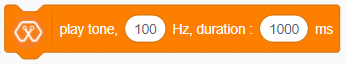
The block generates a tone in the Piezo buzzer connected to the D25 pin on the Magicbit with Selected frequency and selected Duration.

The block generates a selected note(C,D,E,F,G,A,B) for a selected number of beats.

The block rotates the selected DC motor(motor 1 or motor 2) at the selected speed.
Motor 1 — connected to M1A and M1B pins on the Magicbit
Motor 2 — connected to M2A and M2B pins on the Magicbit
Speed — should be at the range of -100 to 100.

The block displays the text you entered at the selected starting position on the OLED display.

The block displays the selected shape(circle, triangle, square) at the selected starting position on the OLED display on Magicbit.

The block sets the font size(supports sizes from 2 to 5) of the text displayed on the OLED display on Magicbit

The block sets the shape size(supports sizes: small, medium, large) of the shape displayed on the OLED display on Magicbit.
The block clears the OLED display, which means all pixels are off.

The block returns the distance by reading the analog pin where the ultrasonic sensor is connected.
![]()
The block returns the temperature by reading the analog pin where the DHT11 sensor is connected.
![]()
The block returns the humidity by reading the analog pin where the DHT11 sensor is connected.

The block sets the color of the RGB module to the selected RGB value. These R, G, B values should be an integer between 1-255. ‘Pin’ variable is the Microbit pin where the RGB module is connected, and the ‘index’ variable represents the number of LEDs that module has.

The Block sets the color of the RGB LED to the selected color at the selected pin on Magicbit.