
Introduction to Magicblocks playground
Magicbit Blocks
Following Blocks are available.
- Digital Out
- Digital In
- Analog Out/PWM
- Analog In
- Serial Tx
- Serial Rx
- Servo
- Display
- Buzzer
- Motor
- DHT11
- NeoPixel
- Ultrasonic
This block set enables you to control individual pins of the device from the playground. The functionality of each block is described below:
How to Configure Blocks
Every block has a property called Device ID, where you need to specify to which device this block belongs. This is important because you will be working with multiple devices in a typical IoT project. You can find the device ID from the Magicblocks device manager.
Digital Out
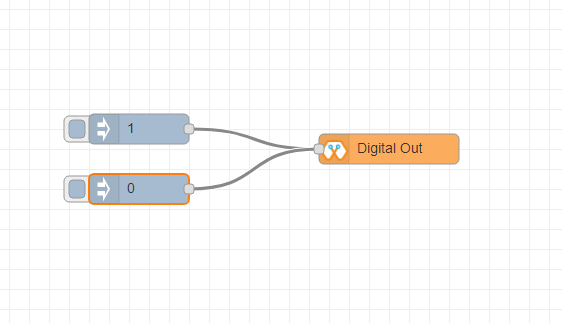
This block is used to set a digital output pin to 1 or 0 based on the input. An input of 1 or true will make the configured pin go HIGH, and vice versa.
-
- Configuration
-
- Pin: pin number of the Digital pin to write to. Available pins can be selected from the dropdown list.
- Name: Any name desired
-
- Input
-
- value to be written to the pin. Accepts 1 (true) or 0 (false) eg: {“payload”: 1}
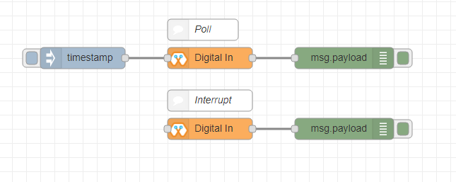
Digital In
This block will read the Input status of a pin. There are two methods to get input 1. Poll — Block needs to trigger to get input status. Any input will serve as a trigger. (EG: inject block) 2. Interrupt — If there is any change of pin state of Magicbit block will output the current state, Input status can be passed to another block or viewed on the debug window.
-
- Configuration:
-
- Pin: pin number of the digital pin to read. Select from the drop-down list.
- Name: Any name desired
- Method: Poll/Interrupt
-
- Input
-
- Any input. Used as a trigger.
-
-
- Output
-
- Value of the pin as 1 or 0 in the following format and the pin number as the topic
-
Analog Out
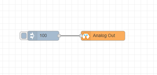
This block is used to set PWM to pins of Magicbit. The value should be in the range of 0-255. An inject block or output of another block can be used to set the value.
-
- Configuration:
-
- Pin: pin number of the to set PWM. Select from the drop-down list.
- Name: Any name desired
-
- Input
-
- Inject block or any block. The input value should be in the range of 0-255
Analog In
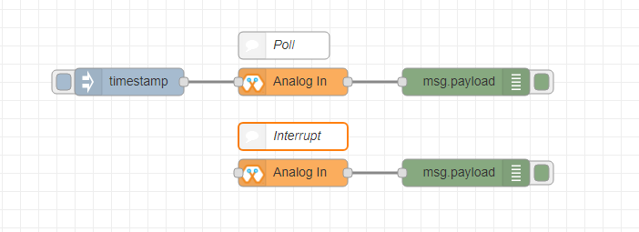
This block will read the analog value of the ADC pin of the module. Similar to the digital in the block, you need to set the method to read the value. Any input sent to the block will serve as the trigger. 1. Poll — Block needs to trigger to get input status. Any input will serve as a trigger. (EG: inject block) 2. Interrupt — If there is any change greater or less than the threshold value of, the Magicbit block will output the analog value.
-
- Configuration:
-
- Pin: pin number of the analog pin to read (Required)
- Name: Any name desired
- Method: Poll/Interrupt
- Threshold: If interrupt method selected value, return from the output if there is any change greater or less than this value
-
- Input
-
- Any input. Used as a trigger.
-
- Output
-
- Value of the pin from 0 to 4096 (12bit ADC) {“payload”: 965}
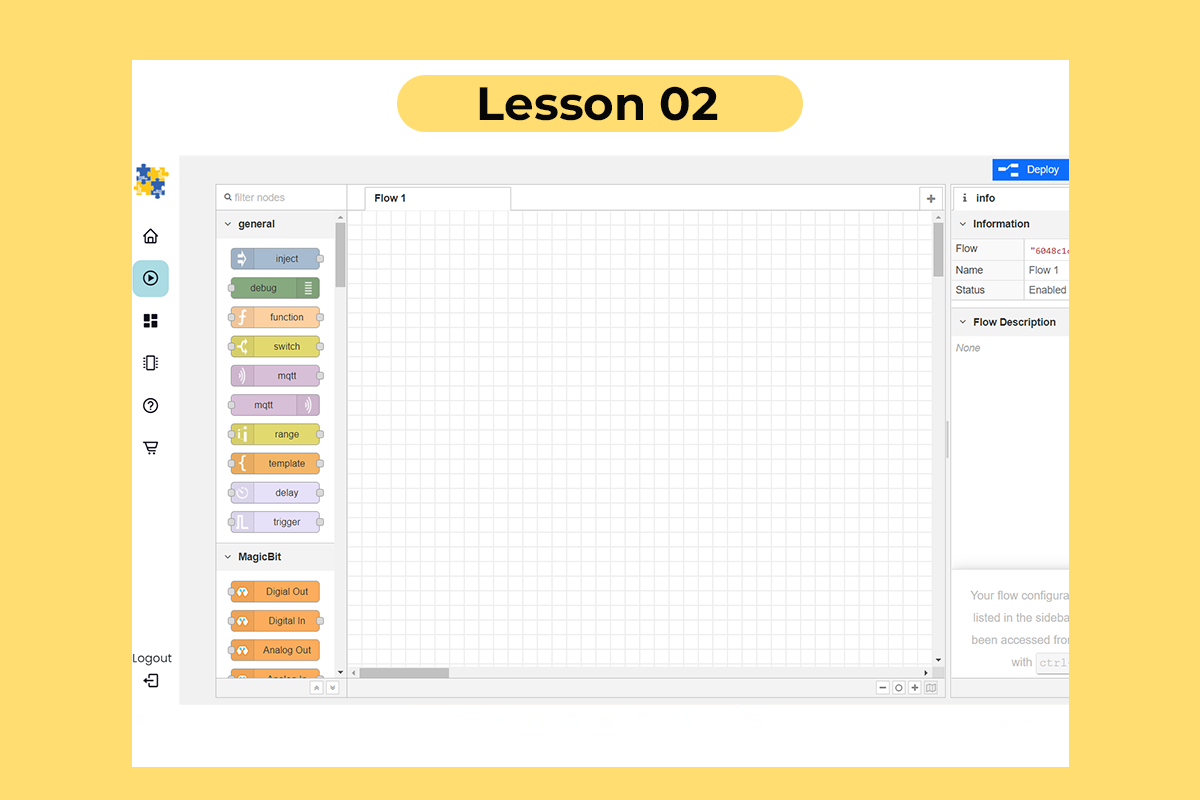
Playground
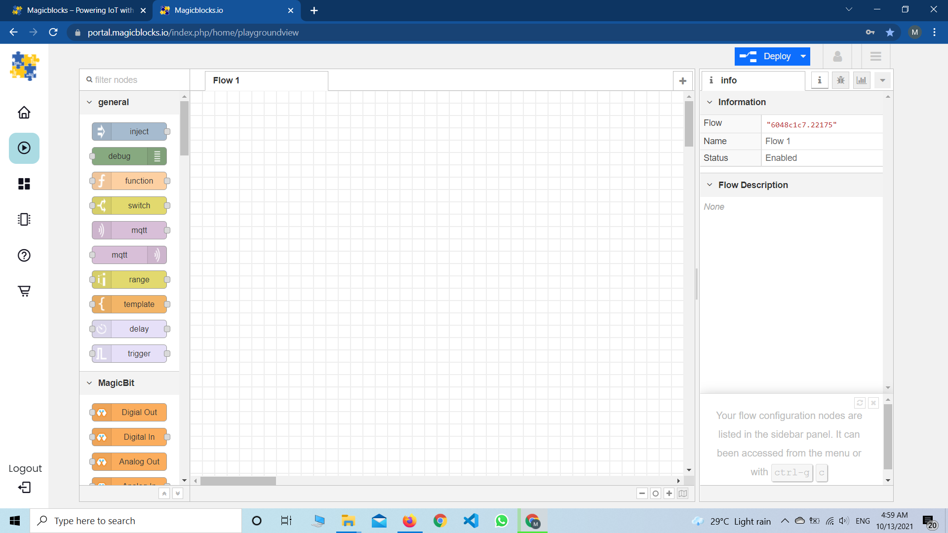
The editor window consists of four components:
- The header at the top, containing the deployment button, main menu, and, if user authentication is enabled, the user menu.
- The palette on the left, containing the nodes available to use.
- The main workspace is in the middle, where flows are created.
- The sidebar is on the right.
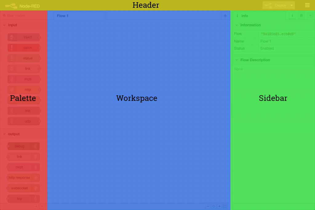
The main workspace is where flows are developed by dragging nodes from the palette and wiring them together. The workspace has a row of tabs along the top; one for each flow and any sub-flows that have been opened.
Flow

Adding a flow
To add a new flow, click the image:: https://github.com/magicbitlk/Magicbit-Magicblocks.io/blob/master/Images/plus.png?raw=true
button in the top bar.
To edit a flow’s properties, double-click on its tab in the top bar. This will open the Flow Properties dialog.
Within the dialog, the flow’s name and description can be set. The description can use Markdown syntax for formatting and will appear in the Information sidebar.
The Status property can be used to disable or enable the flow.
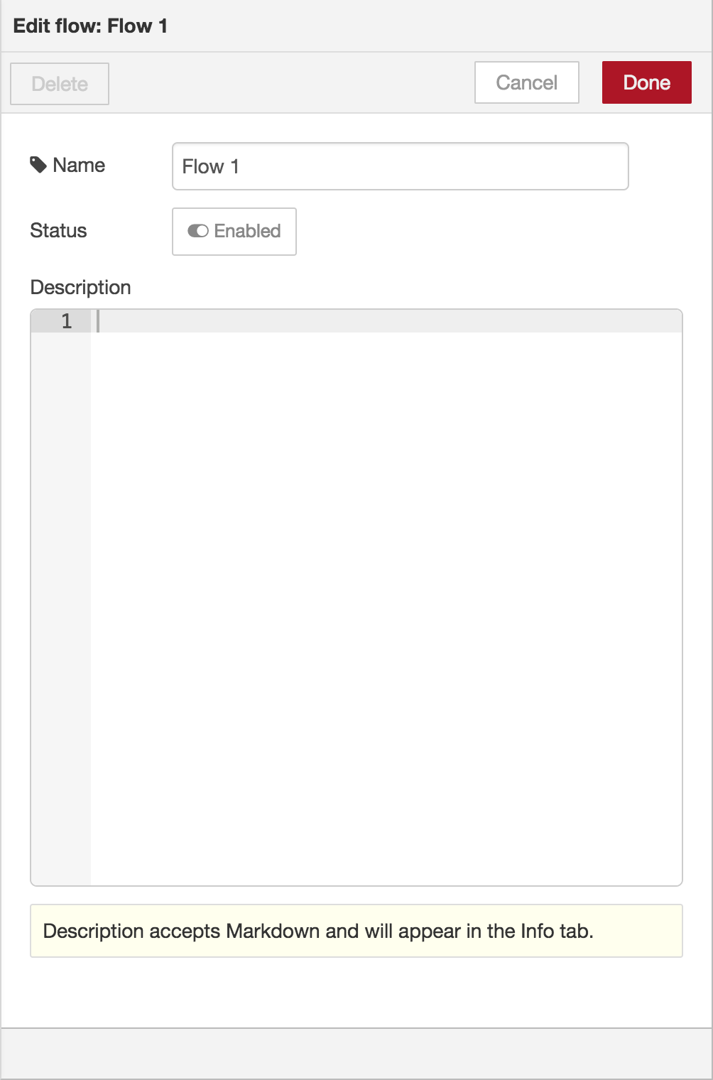
Deleting a flow
To delete a flow, click the ‘Delete’ button in the Flow Properties dialog.