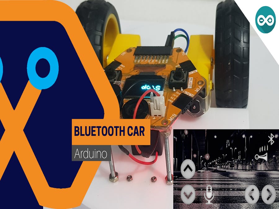
Bluetooth Control Car Using Magicbit
Make Bluetooth control remote car using only Magicbit
Components Required


Story
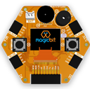
Hey guys, today we will learn about how to make a Bluetooth control remote car using Magicbit Dev. board. The special thing is, in this build we don’t use any external motor driver or bluetooth module. Because Magicbit already have both things. So lets gets start.
Theory and Methodology
The theory is very simple. we send data to Magicbit from using our remote. Then Magicbit reads that data and then controls the motors according to that commands. In this case, our remote is smart phone. To communicate with Magicbit, we use specific app. You can find many types of apps from play store or app store to do that. We used serial data protocol for sending the data. When we power on the Magicbit, it searching bluetooth devices around it. Then it connect with relate device and get data from it. According to the data which sent by the smart phone, the ESP32 processor of the Magicbit will generate motor driver signals. These signal will use by the inbuilt motor driver of the Magicbit for control both motors.
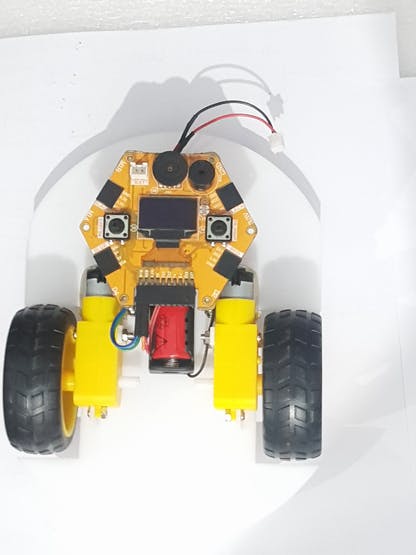
Hardware Setup
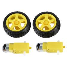
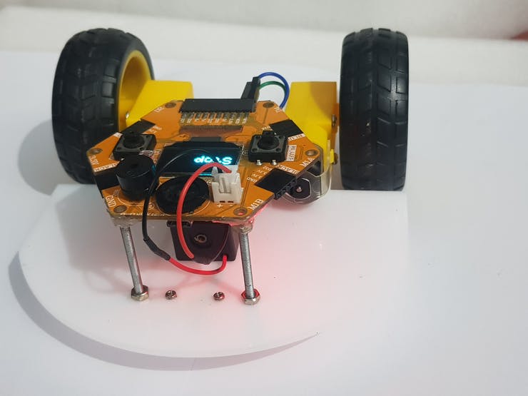
This part is depend on your creativity. You can use any type of 3V DC gear motors, proper wheels and some plastic or wood chassis to fit magic bit, motors and battery case. In our design we designed our own shape to chassy using Solidworks and then we used laser cutting techniques to cut shape in the acrylic sheet. Then we fitted all components on it.
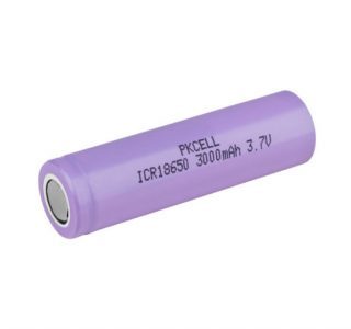
The wiring diagram is also very simple. Because we only have connect battery, Magicbit and motors. For batteries I used one 3.7V 18650 Li-ion battery. To hold the battery we use Li-ion single cell battery case. The wiring diagram is shown below.
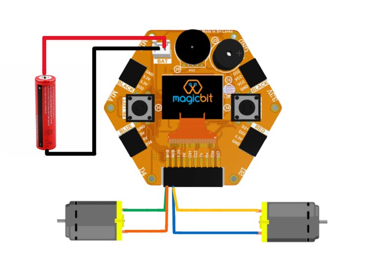
In this configuration we don’t use switch to power on the car. Because when I want to power on the car I connect the power connector to Magicbit. But you can use external switch to powering the car.
Software Setup
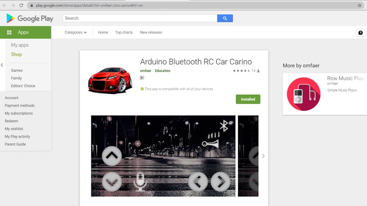
This have two sub parts. First one is mobile application part and the second one is Arduino programming part. So lets look at our first part. To control our car we use “Carino” bluetooth app where available in play store. But you can find bunch of apps to control the remote car. Going to that play store and install that app. If you using Iphone you can use other app to connect with Magicbit. To connect with Magicbit, click the bluetooth symbol on the app and choose the ESP32 device. After small time your phone will connect with Magicbit. Now your remote is ready.
In the Arduino code we bluetooth library for establish ESP32 and other devices. This library is already included in your Magicbit library. In the main function we search other devices. If Magicbit is connect with some other device, then it will beginning to receiving data. So in the loop function we check if there any data is available. If some data is available we stored that data in variable. This data type is characteristic data type. If we click some vehicle controlling command button then Magicbit received that data and generate motor outputs according to command. In the app we can’t change the character. But in other apps we can change that key values as we like. After stored that character we compare that with defined characters of the movements. So if they are equal the robot move according that command. The LCD part is optional. If you want you can remove it. To control the motors we use 16, 17 18 and 26 GPIO pins of ESP32. When we want to turn on the motors, we should high one pin and low other pin. To reverse the direction we have reverse the signals. Important thing is we didn’t use addition PWM pins to control the speeds. Because we give PWM signal through high state pin. In this case we don’t use PWM theory. We only want to do turn on and off the motors.
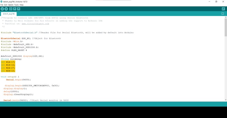
Select COM port and board type as Magicbit and upload the code. First check your motor directions are correct while running. If not then change configuration of the pins of the motors in the code. Now you have very simple bluetooth control small car.
Code
#include "BluetoothSerial.h" //Header File for Serial Bluetooth
BluetoothSerial ESP_BT; //Object for Bluetooth
#include <Wire.h>
#include <Adafruit_GFX.h>
#include <Adafruit_SSD1306.h>
#define OLED_RESET 4

Adafruit_SSD1306 display(128, 64);
String incoming;// varible store received data
int M1A = 17; // motor pins
int M1B = 16;
int M2A = 27;
int M2B = 18;

void setup() {
  Serial.begin(9600);

  display.begin(SSD1306_SWITCHCAPVCC, 0x3C);
  display.display();
  delay(1000);
  display.clearDisplay();

  Serial.begin(9600); //Start Serial monitor in 9600
  ESP_BT.begin("ESP32_Blutooth_car"); //Name of your Bluetooth Signal
  Serial.println("Bluetooth Device is Ready to Pair");
  pinMode(M1A, OUTPUT); // configure outputs
  pinMode(M1B, OUTPUT);
  pinMode(M2A, OUTPUT);
  pinMode(M2B, OUTPUT);

}

void loop() {

  if (ESP_BT.available()) //Check if we receive anything from Bluetooth
  {
    incoming = char(ESP_BT.read()); //Read what we received
  }
  Serial.println(incoming);
  if (incoming == "F") { // forward
    Serial.println("Forward");
    Display("Forward");
    Forward();
  }
  else if (incoming == "B") { // reverse
    Serial.println("Reverse");
    Display("Reverse");
    Backward();
  }
  else if (incoming == "R") { //turn right
    Serial.println("Right");
    Display("Right");
    Right();
  }
  else if (incoming == "L") { // turn left
    Serial.println("Left");
    Display("Left");
    Left();
  }


  else {
    Stop();

    Display("Stop");
  }
  delay(20);
}

void Forward() {

  digitalWrite(M1A, HIGH);
  digitalWrite(M1B, LOW);
  digitalWrite(M2A, HIGH);
  digitalWrite(M2B, LOW);

}

void Backward() {

  digitalWrite(M1B, HIGH);
  digitalWrite(M1A, LOW);
  digitalWrite(M2B, HIGH);
  digitalWrite(M2A, LOW);

}
void Right() {

  digitalWrite(M1A, HIGH);
  digitalWrite(M1B, LOW);
  digitalWrite(M2B, HIGH);
  digitalWrite(M2A, LOW);

}
void Left() {

  digitalWrite(M1B, HIGH);
  digitalWrite(M1A, LOW);
  digitalWrite(M2A, HIGH);
  digitalWrite(M2B, LOW);

}

void Stop() {
  digitalWrite(M1B, LOW);
  digitalWrite(M1A, LOW);
  digitalWrite(M2A, LOW);
  digitalWrite(M2B, LOW);

}


void Display(String commond) { // display data
  display.clearDisplay();

  display.setTextSize(3);             // Normal 1:1 pixel scale
  display.setTextColor(WHITE);        // Draw white text
  display.setCursor(0, 20);            // Start at top-left corner
  display.println(commond);
  display.display();

}
If you need help or couldn’t understand a step be sure to check out our youtube video by clicking here: Youtube Video