

RGB Module
Change colors of the RGB LED as required
Components Required
Introduction
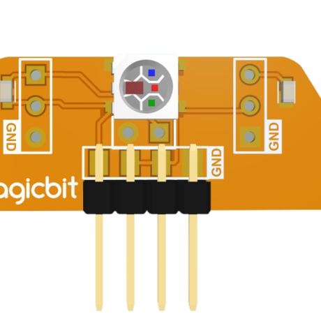
An RGB LED has 4 pins, one for each color (Red, Green, Blue) and a common cathode. It has three different color-emitting diodes that can be combined to create all sorts of colors. R- Red G- Green B- Blue.
Learning outcomes:
- Using an RGB LED and changing its color as the required
Theory
The RGB color model is an additive color model in which red, green, and blue light are added together in various ways to reproduce a broad array of colors. The name of the model comes from the initials of the three additive primary colors, red, green, and blue. The main purpose of the RGB color model is for the sensing, representation, and display of images in electronic systems, such as televisions and computers, though it has also been used in conventional photography. Before the electronic age, the RGB color model already had a solid theory behind it, based on human perception of colors.
Methodology
As usually connect the RGB module to your Magicbit, for this, we take data pin as pin 32. Create the following Script by Dragging and Dropping blocks from the Block Palette.
Script
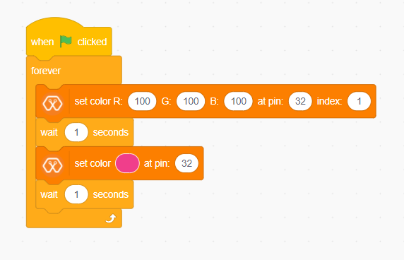
Explanation
In this example, we are using a single RGB LED. This example changes RGB LED color into two colors continuously. This program also starts by clicking the green flag. Then forever block is responsible for continuously running the script inside it. The first block inside the forever block sets the color of the LED to the color represented by R:100, G:100, B:100. In this block, the pin represents the LED connected pin to Magicbit and here it is D32. The index represents the number of LEDs in the RGB module. Then the LED stays in this color for one second and changing its color to the color indicated by the next block. With this block, you can easily select your preferred color.