
Inbuilt motor controller
Use inbuilt motor driver to control motors
Components Required

Introduction
There are many projects where we have to use motors for many purposes. All processors work under 5V or 3.3V. So their outputs are not enough to supply larger current and voltages to control motors. In this case we use an additional module to control motors. That is a motor driver. As the name suggests, every motor driver is doing the same thing. That is , controlling motors using external power sources based on microcontroller signals. These controlling signals are not constant voltage values. They are PWM(Pulse width modulation) signals. These signals are digital signals. Lot of motor drivers use the H-Bridge mechanism to control the motors. If you use an Arduino board you have to use an external motor driver to control motors. But in the Magicbit you don’t want to buy any external motor controllers. Because it already has an inbuilt H-bridge motor driver. So you can directly connect motors to the Magicbit and you can play with them.
Learning outcomes:
- Using inbuilt motor driver to control motors
- Apply motor controlling process for projects
Theory
First let’s look at how this whole process is happening. We all know about that every motor needs power source to work. So if you bought 3v motor you have to supply 3V for proper working. The passing current through the motor is depend on torque of the motor. If motor axel is working freely then it gets low amount of current. If motors are in difficult condition to rotate there axel then it gets higher amount of current. To control motors we used voltage sources. Voltage sources are sources which supply any amount of current under constant voltage. So the speed of motors will depend on the voltages. If we supply high voltage then motor will work at higher RPM and vice versa. Therefore now you can understand that we can control the speed by controlling the supply voltage level. But this is an old way and it’s not efficient and accurate. Modernly we use PWM pulses. PWM means pulse width modulation. In this case we generate a square wave with some constant frequency to control the motors. So the lower state of this wave is nearly zero volt (0V) and the higher state of the wave is nearly supply voltage. Therefore we are able to use our full supply voltage to control the motors. But how can we control the motor speeds using this theorem. That is very easy. If we consider one cycle (duty cycle) of the wave that includes two parts. One is the High stage part and the other one is Low stage part. Let’s say High stage time duration is T1, Low stage Time duration is T2 and one cycle time duration is T. So we can simply write the equation below.
T=T1+T2
If T2=0 and T=T1,then there isn’t any lower state part in every cycle. In this case motor is working with full speed. Because we always give source voltage to motor. But if T1=0 and T=T2, there is no supply voltage and current to the motor. In this case motor is fully turned off. So the speed will be zero. Let’s look at another situation. Lets say T1=T2 ,then T1=T2=T/2. So at this time both time periods of high and low states are equal to every cycle. Now the average value of the wave is half of the source power. Therefore the supply voltage to the motor is half of the main supply voltage(we don’t know the variation between the supply voltage and the motor speed. because it depends on your motor. Therefore we can’t say the motor speed will be half of the maximum speed under half of supply voltage). In this way we can get every voltage between 0 and source voltage from average voltage by changing the ratio between T1 and T2. To measure the PWM signal average, we use some factor value called duty cycle value. This value is a percentage value of the ratio of T1 and T.
Duty cycle=(T1/T)x100%
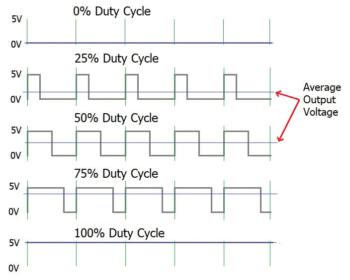
In the microcontrollers we represent this duty cycle value from bit value. If we use 8 bits then we can get 0-255 range to represent duty cycle. In that case 255 means 100% duty cycle and 0 means 0% duty cycle and so on. Now you have some general idea about motor control signals. These PWM signals are not limit to motor controlling applications. These signals are used for many purposes. Next look at how can we use this theorem to motor controlling process. To control motors we use a microcontroller to generate PWM signals. As the introduction describes, these voltage ranges and current of the PWM signals are not sufficient to control the motors. So we used motor driver for that purpose. All we know is that motors can rotate in two opposite directions with various speeds. Because of that reason we get two outputs from the microcontroller to control motor. If we want to rotate the motor in one direction then we use one output to generate a PWM signal while the other one is in low state. If we want that motor rotates in the opposite direction, in that case we use a second output pin to generate a PWM signal while setting the low state to the first pin. Because of the lack of current and voltage of this pin outputs, we will use motor controller unit. This unit includes an H-bridge switching mechanism. Let’s look at how it works. Before moving to that part, take a look at what transistor is. Transistor is a semiconductor device which is used to control signals. There are a lot of transistor types. But every transistor works in the same principle. A transistor has three pins. One pin is used to supply the signal. These signals can be voltage or current signals. The source current is going through other pins. According to the input signal this flowing current is changing. If input signal is larger than some defined value then the passing current will be maximized and if input signal is lower than some amount, then the passing current will be nearly neglectable. So these 2 situations are known as cutoff and saturation regions of the transistor. At these stages the transistor works as a switch. So if we connect microcontroller output into the transistor input signal, then at the high digital signal transistor will be on and at the low digital signal transistor will be off. Now you have a basic idea about transistor mechanisms.
So now let’s look at the H-bridge mechanism.
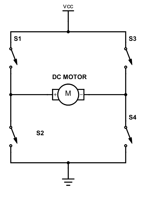
As you can see there are four switches s1, s2, s3 and s4. These switches are actually transistors or some switching component. Let’s analyze this diagram. If s1 and s4 are ON and others are OFF then, the motor will work in one direction. By changing the ON and OFF time of the S1 and S4 with some constant frequencies, we can rotate that motor with various speeds. If s3 and s2 are ON and others are OFF then the motor will go in the other direction. Also we can change the motor speed by changing the ON and OFF time of S2 and S3 switches. If all switches are OFF or all are ON then the motor will stop.
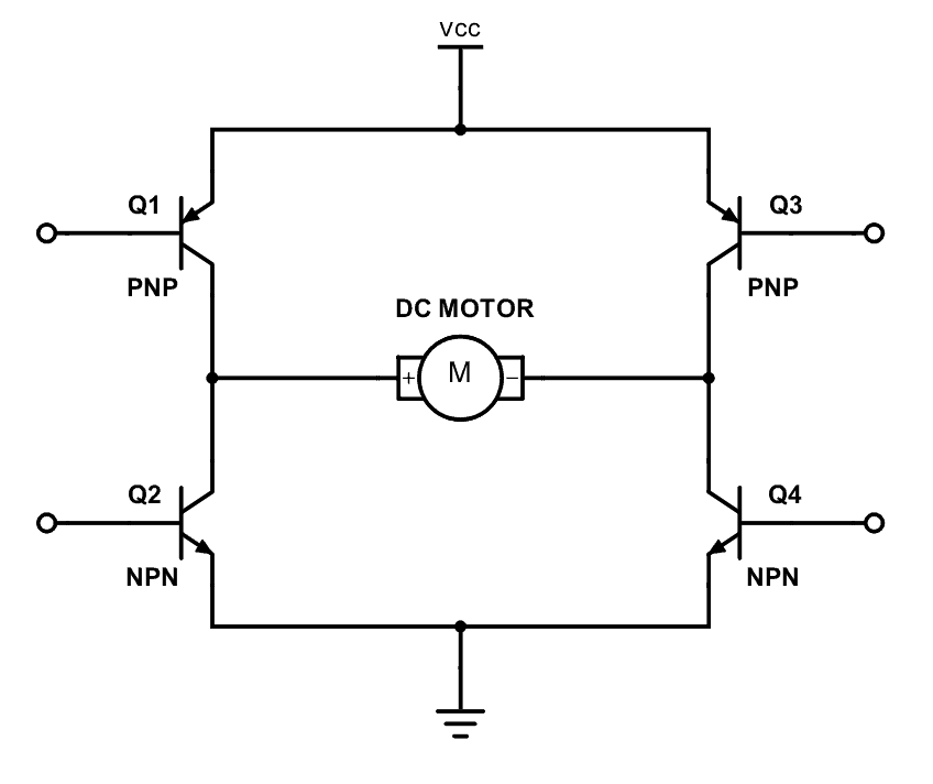
So now you can see how switches are replaced by transistors. Q1, Q2, Q3 and Q4 represents S1, S2, S3 and S4 switches. In this diagram the base pin is the input signal pin of the transistor. If we supply a high state signal to that pin the transistor will saturate and that transistor acts as a closed switch (ON). Otherwise it will act as an open (OFF) switch. In this diagram there are four inputs to control for transistors. But we combine these four inputs to two inputs which satisfy the above switching conditions.
In the Magicbit it includes L110 motor driver IC which has the ability to control two motors. So it is a two channel motor driver IC. It internally connected to the esp32 processor of the Magicbit from four. M1A, M1B, M2A and M2B are the pins of the lower port of the Magicbit which are output pins of the L9110 IC.
Methodology
In this example, we are going to use M1A and M1B pins. Connect the motor to the M1A and M1B pins of Magicbit. Then create the following script by dragging and dropping blocks on the scripting area.
Script
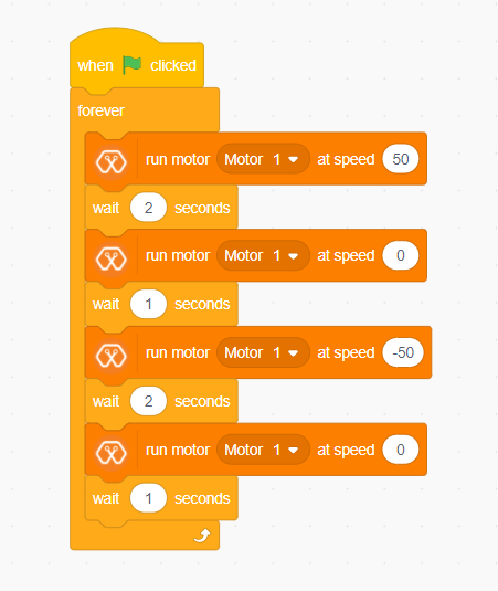
Explanation
In this example, we are going to continuously rotate the dc motor in one direction and to the opposite direction. As other examples, clicking the green flag on the MagicCode interface starts the program. Then the “forever” block continuously runs the script inside it. First, the motor rotates in one direction for two seconds. Then it stops for another one second and starts to turn in the opposite direction. You can set the speed of the selected motor as you want with the MagicCode “Run motor [Motor] at speed [Speed]” block.