Use the potentiometer on the Magicbit using Magicblocks
Components Required
Story
Hello and Welcome, This tutorial will teach you to use the potentiometer on the Magicbit using Magicblocks by using the Inject Block. We will be controlling the brightness of an LED using the potentiometer.
First, log into your Magicblocks account,
Magicblocks is easy visual programming software for the program of your Magicbit. Anyone can program their microcontroller by using magicblocks.io and there is no need for programming knowledge. You can sign up for free.
Start and Open the Playground.
Next, make sure your Magicbit is connected to the internet and plugged in, and also linked to your account through Device Manager.
All Done? Then scroll down to Method 1
Set up the Analog in Block
1. Drag & Drop the “Analog in” block from the Magicbit nodes section to the flow.
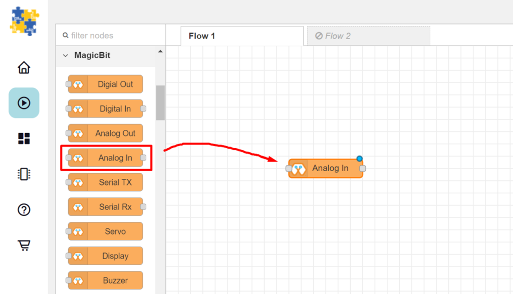
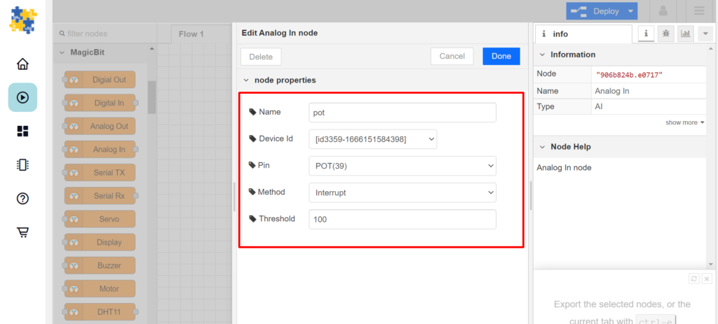
2. Double click the “Analog In” node to open it’s configuration page and configure the node as described below.
- Name : Give it a any name to identify.
- Device ID : Select your unique Device ID from the drop-down menu.
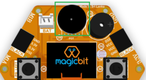
- Pin : Select POT(39) to address the potentiometer
- Method : Select Interrupt, as we need to measure potentiometer continuously
- Threshold : The output of this node can vary from 0 to 4096. The threshold of the node is the amount the value needs to change for the node to give an output. For this project we will use 100.
Set up the Switch Block
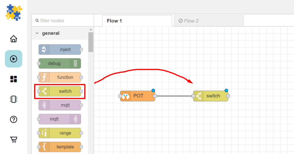
3. Drag & Drop the “Switch” block from the Magicbit nodes section to the flow.
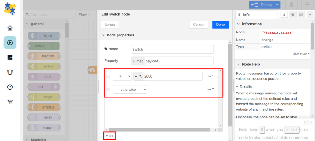
4. Configure the switch block as shown:
- Use the drop-down menu to select “>” and type “2000” in the field next to it.
- Click the “add+” button to add one more option.
- Use the drop-down menu to select “otherwise”. This directs the message to output 2
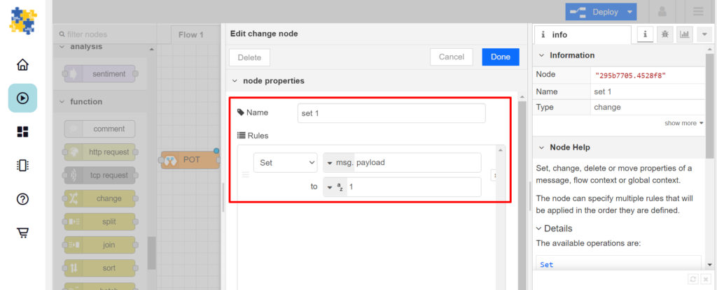
Set up the Change block
(This Node is used to activate change the message to either “0” or “1”)
1. Drag & Drop the Change Block from the function nodes section on the left of the screen to the flow.
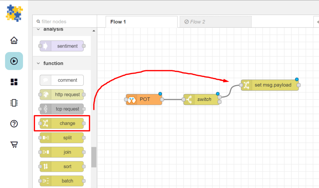
3. Configure the change node as shown.
- Give it a name and configure to set payload to “1”.
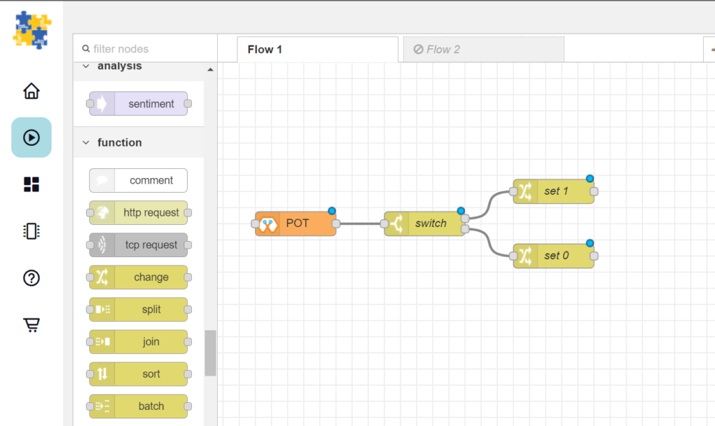
4. Duplicate the change block and configure the new block to set value to “0”.
- It is configured the dame as step three but here payload should be set to “0”.
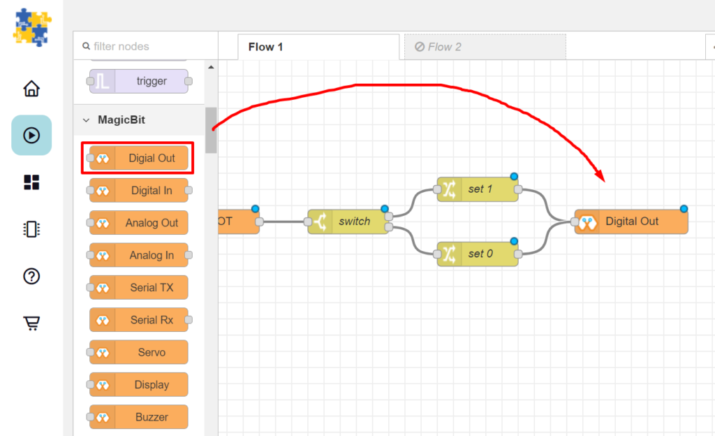
Setup the Digital Out Block
5. Add a “Digital Out” block and connect it as shown.
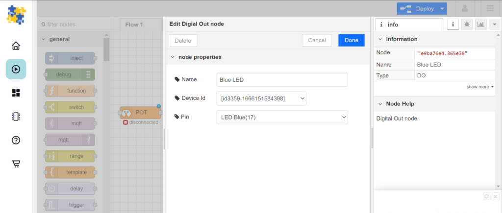
6. Configure the Digital Out Block as shown.
[Optional] Import Already Setup Nodes
If you had trouble setting up nodes, you can use the import feature in Magicblocks to get the nodes which have been already set up.
- First copy this code to your clipboard;
[{"id":"906b824b.e0717","type":"AI","z":"430aa33e.f67e4c","name":"POT","epId":"id3359-1673348308190","pin":"39","method":"1","threshold":"100","x":230,"y":200,"wires":[["f6b88a15.331c38"]]},{"id":"f6b88a15.331c38","type":"switch","z":"430aa33e.f67e4c","name":"switch","property":"payload","propertyType":"msg","rules":[{"t":"gt","v":"2000","vt":"str"},{"t":"else"}],"checkall":"true","repair":false,"outputs":2,"x":410,"y":200,"wires":[["295b7705.4528f8"],["828c41f2.858a1"]]},{"id":"295b7705.4528f8","type":"change","z":"430aa33e.f67e4c","name":"set 1","rules":[{"t":"set","p":"payload","pt":"msg","to":"1","tot":"str"}],"action":"","property":"","from":"","to":"","reg":false,"x":570,"y":160,"wires":[["e9ba76e4.365e38"]]},{"id":"828c41f2.858a1","type":"change","z":"430aa33e.f67e4c","name":"set 0","rules":[{"t":"set","p":"payload","pt":"msg","to":"0","tot":"str"}],"action":"","property":"","from":"","to":"","reg":false,"x":570,"y":240,"wires":[["e9ba76e4.365e38"]]},{"id":"e9ba76e4.365e38","type":"DO","z":"430aa33e.f67e4c","name":"Blue LED","epId":"id3359-1673348308190","pin":"17","x":740,"y":200,"wires":[]}]- Click on the options menu on the top right-hand corner of the screen.
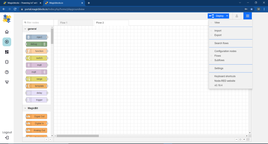
- Next, hover your cursor over the Import sub-menu.
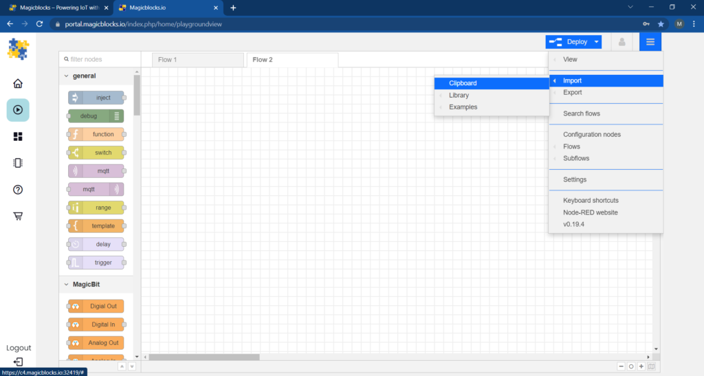
- Then click on Clipboard and paste the code on your clipboard to the text field
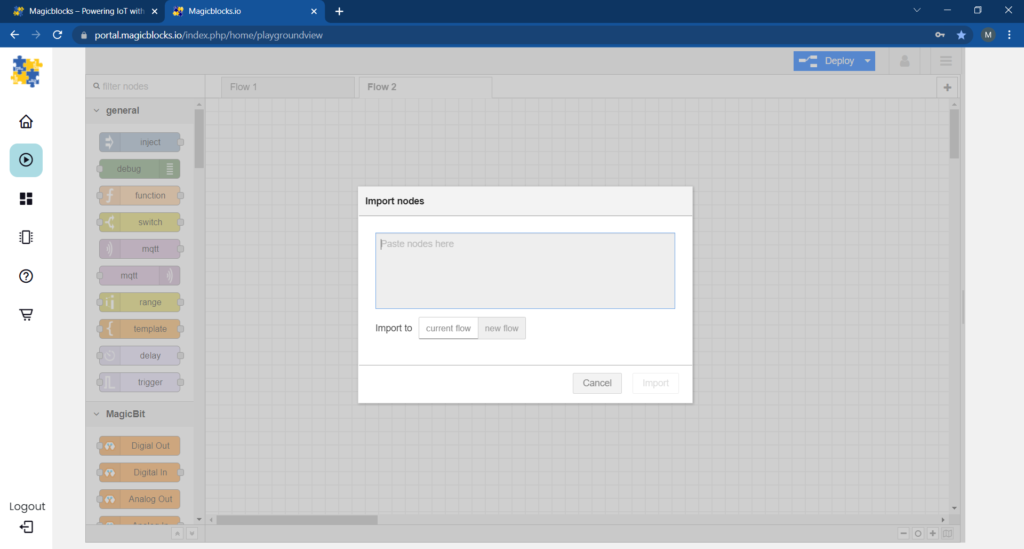
- Select current flow or new flow and click on Import.
IMPORTANT
Make sure you type your device ID on the “Analog in” and “Digital out” node properties.
Finally, Deploying the Blocks
- Make sure all blocks are connected.
- Click on the Deploy button on the top right-hand corner of the screen.
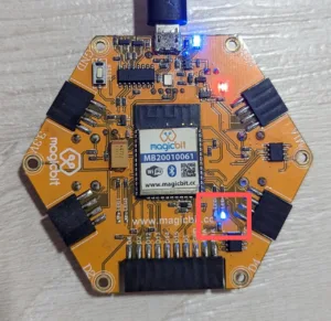
- Try rotating the potentiometer, when the reading becomes higher than 2000, the blue LED turns on. otherwise it turns off.
Troubleshooting
- Check whether your Magicbit is connected to the internet.
- Check whether the Device ID is correct on the “Analog in” and “Digital out” node properties.
If you need help with the steps, be sure to follow our video tutorial on YouTube.