Tilt Sensor
Tilt sensor acting as a switch
Components Required
Introduction
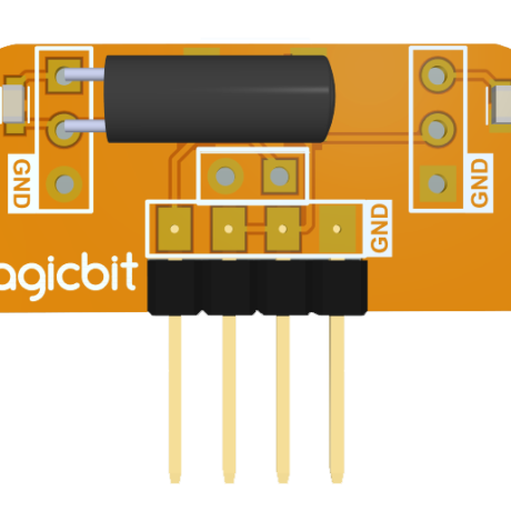
In this example, you are learning how to use a Tilt sensor. Tilt sensor produces digital outputs such as high and low. Therefore, the tilt sensor works as a switch that gives on and off states.
Learning outcomes
- Digital reads and print them on the serial monitor
- Working principle of the tilt sensor
Theory
When the device gets power and is in its upright position, then the rolling ball settles at the bottom of the sensor to form an electrical connection between the two end terminals of the sensor.
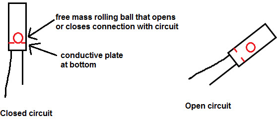
Figure 1: Working principle of tilt sensor [1]
Methodology
As the first step, you should connect a Magicbit tilt sensor to the Magicbit core board. For this, you can use one side connector from four-side connectors of the Magicbit core board or if you want to extend the length of the connection, you can use jumper wires. For this example, the tilt sensor was connected to the upper left connector of the Magicbit core board. Then connect the Magicbit to your pc and upload the code. You can get outputs using a serial monitor.
Code
const int TILTpin = 32;

void setup() {
  Serial.begin(9600);
  pinMode (TILTpin, INPUT);
}

void loop() {
  Serial.println(digitalRead(TILTpin));
  delay(100);
}
- Outputs: Serial monitor
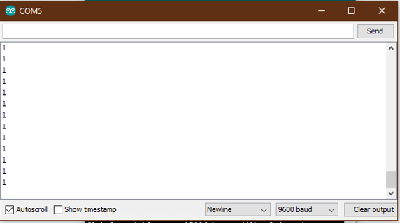
Figure 2: High state of the tilt sensor
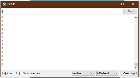
Figure 3: Low state of the tilt sensor
Explanation
Const int TILTpin: Defining input pin digitalRead: Read the data input of configured data pin.


